We see it frequently in the field: a personal cooling suit system is deployed, and the initial tests look good. But under sustained, real-world conditions, the cooling can’t be maintained. The most common complaint we investigate isn’t a failure of the cooling unit itself, but a system-level failure where the limiting factor is power availability under dynamic load. The system provides cooling, but it cannot be sustained continuously, leading to performance degradation or intermittent shutdowns. This is a classic integration challenge where the power source and the cooling unit are not correctly matched for the application’s peak demands.
This is a sizing problem rooted in electrical engineering, not just thermodynamics. By the end of this post, you’ll be able to identify the critical decision gates for sizing the power and thermal management systems for a micro dc aircon for cooling suit applications, ensuring you can deliver sustained performance instead of just short-term cooling.
Field Snapshot: Sizing a micro dc aircon for cooling suit power systems
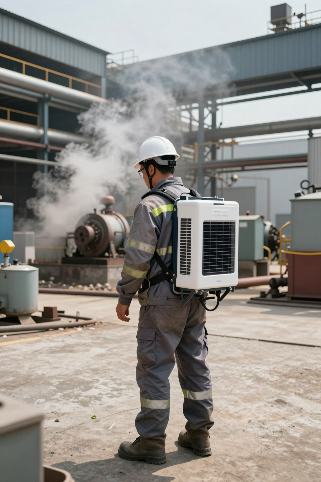
The scenario is a familiar one. An integrator has designed a wearable cooling vest for an industrial operator who works in high-ambient-heat environments. The system uses a miniature vapor-compression air conditioner powered by a battery pack. During bench testing, everything works. In the field, however, the operator reports the system cuts out, especially when they are moving around or when the ambient temperature peaks mid-day. The battery appears to have sufficient capacity on paper, yet the runtime is unpredictable. The core issue is that the power system was sized for the continuous load, not the dynamic, peak-demand nature of a micro-compressor.
This is where we, as integration engineers, have to shift our thinking from steady-state specifications to real-world operational constraints. The datasheet shows a continuous draw, but the compressor’s startup sequence is what defines the stability of the entire system.
First Checks in the Field
When we encounter a system that fails to sustain cooling, we don’t start at the compressor. We start at the power source and work our way forward. These are the first three things we check on-site.
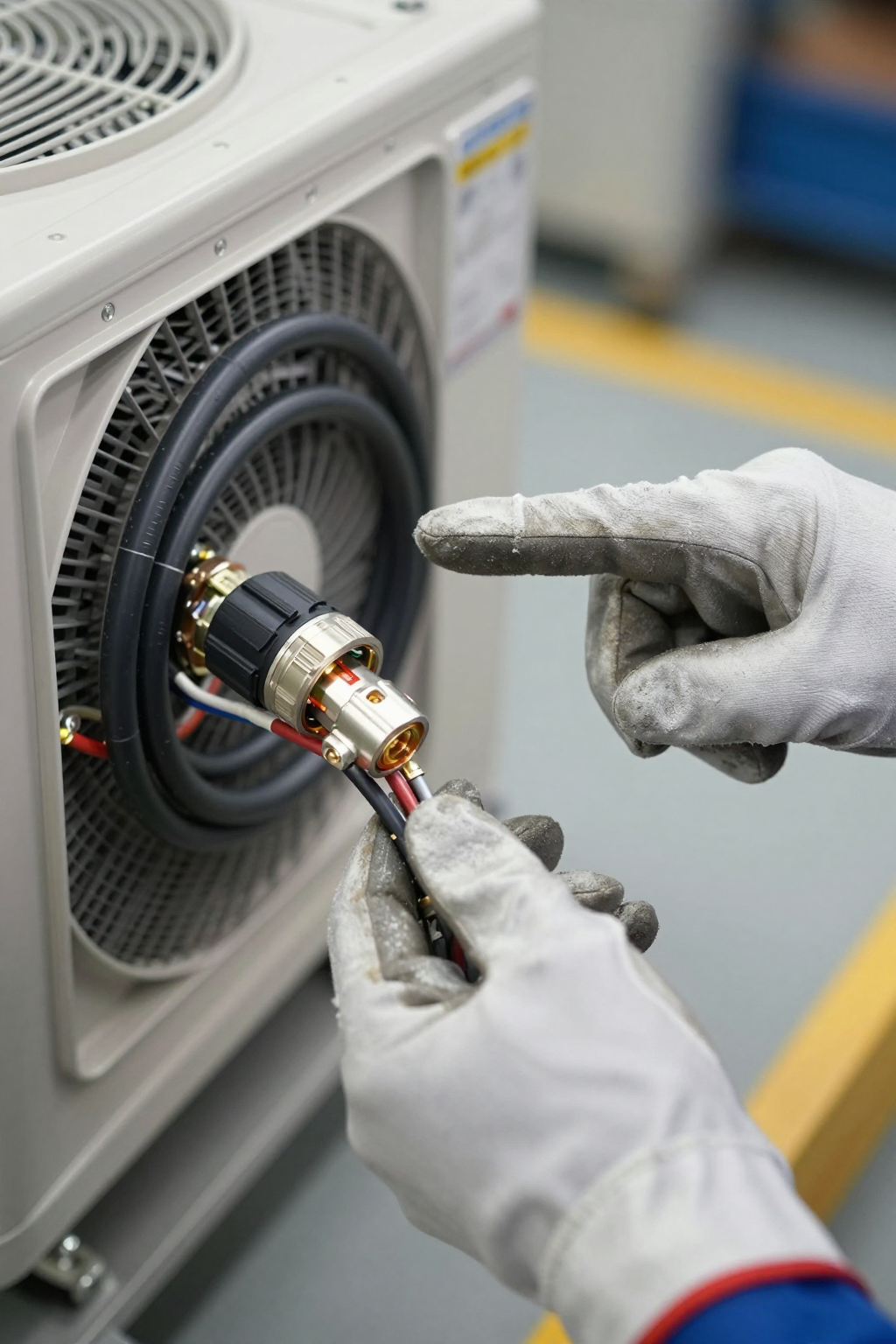
- Check: Power supply voltage under load, specifically at startup.
Why: The micro-compressor has a high inrush current. The brief surge required to start the compressor can cause a momentary but significant voltage drop if the power source or wiring is undersized.
What it suggests: If the voltage sags significantly, the unit’s control board may register a fault and prevent startup or shut down to protect the electronics. This points to an issue with the power supply’s peak current delivery capability or high resistance in the wiring. - Check: Condenser air intake and exhaust paths.
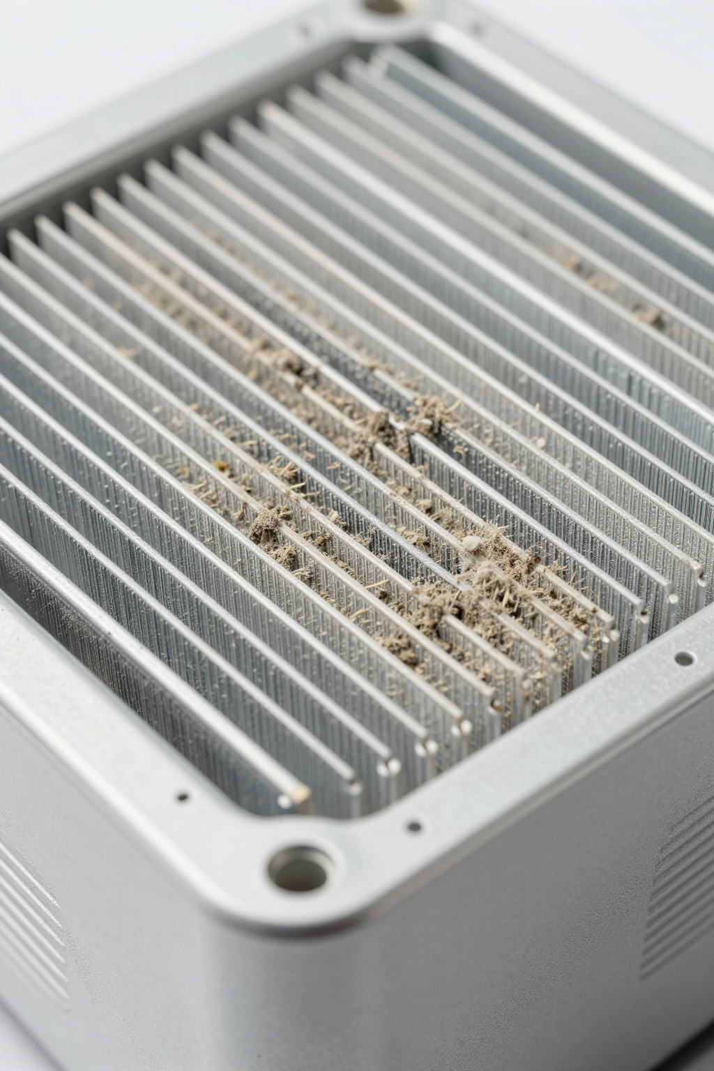
Why: A vapor-compression system works by moving heat from the user to the ambient environment. The condenser is where this heat rejection happens. Any obstruction severely limits the system’s ability to cool effectively.
What it suggests: Blockages from dust, debris, or proximity to other equipment force the compressor to run longer and harder to achieve the same cooling effect. This increases the average power consumption, draining the battery faster and putting more thermal stress on the components. - Check: Actual operating ambient temperature versus the system’s design specifications.
Why: The cooling capacity of any air conditioning system is relative to the ambient temperature. As the outside temperature rises, the system must work harder to maintain the same temperature differential.
What it suggests: The system might be operating at the edge of or outside its specified operating temperature range (up to 55°C). This can lead to continuous, non-cycling operation, which maximizes power draw and can exceed the thermal design of the power supply and connectors.
Common Failure Modes & System Constraints
Understanding why a system fails is key to designing one that succeeds. In our experience with personal cooling applications, the issues are rarely defects in the cooling unit; they are almost always related to system integration. Here are the most common failure modes we encounter.
- Symptom: The system fails to start or trips the power supply’s protection circuit.
Likely Cause: Underestimating the peak inrush current. The system may draw 18A continuously, but the startup spike can hit 33A.
Why it Matters: Power supplies, especially battery management systems (BMS), are often designed with over-current protection that can be triggered by this spike. Sizing your power source and wiring for the continuous draw alone is a common design flaw. - Symptom: Cooling performance is strong initially but fades over 30-60 minutes.
Likely Cause: Progressive heat soak due to blocked condenser airflow.
Why it Matters: The condenser fins are the system’s radiator. If they are clogged with dust or the unit is mounted without adequate clearance, the refrigerant cannot release its heat. This causes system pressure to rise, increasing compressor load and power draw until performance collapses. - Symptom: The cooling unit shuts down randomly, even when the battery is not depleted.
Likely Cause: Unstable voltage from an unregulated power source.
Why it Matters: The control electronics require a stable 12V DC supply. Voltage spikes or sags from shared power sources (like a vehicle’s electrical system) or unregulated battery packs can cause the control board to fault and shut down as a protective measure. - Symptom: The user reports excessive vibration or noise.
Likely Cause: The micro-compressor’s vibration is being directly transferred to the chassis or enclosure.
Why it Matters: While the unit itself operates at around 60 dBA, improper mounting can cause resonant frequencies in the larger structure, amplifying noise and potentially affecting nearby sensitive electronics. - Symptom: Evidence of moisture or corrosion inside the equipment housing.
Likely Cause: Poor condensate management.
Why it Matters: Cooling air below its dew point will produce condensation. In humid environments, this is a certainty. Without a planned drainage path, this water will pool, posing a significant risk to any electronics in the enclosure.
Decision Gates for System Sizing
To avoid these failure modes, your design process must pass through several critical decision gates. Answering these questions with real-world data will lead to a robust and reliable system.
Gate 1: Can Your Power Source Handle the Peak Current?
- Constraint: The system requires a power source capable of delivering 33A for short durations during compressor startup, while maintaining a stable voltage.
- Decision Trigger: Does your specified battery pack, power supply, or vehicle circuit have a maximum discharge rating that provides sufficient headroom above 33A? Have you accounted for voltage drop across the entire wiring harness?
- Engineering Resolution: If the power source is borderline, the solution is not to hope for the best. You must either specify a power source with a higher peak current rating or implement a power conditioner or soft-start circuit to manage the inrush. All wiring, fuses, and connectors must also be rated for the peak current, not the 18A continuous draw.
- Integration Trade-off: A higher-rated power supply increases cost, weight, and size—all critical factors in a wearable application. Adding power conditioning electronics increases complexity and introduces another potential point of failure, but it may be necessary for systems with strict power source limitations.
Gate 2: Is the Thermal Load Realistically Calculated?
- Constraint: The cooling unit provides a nominal cooling capacity of 450W within its operating temperature range of 0°C to 55°C.
- Decision Trigger: Have you calculated the total heat load? This includes the user’s metabolic heat output (which varies with activity), solar gain, and heat from any other onboard equipment. Does this total load exceed 450W at the highest expected ambient temperature?
- Engineering Resolution: If the calculated heat load consistently exceeds the unit’s capacity, the compressor will run 100% of the time. This maximizes power consumption and eliminates any buffer for handling peak loads or hotter-than-expected conditions. The primary solution should be to reduce the incoming heat load first—through better insulation in the garment, for example—before considering a larger cooling system.
- Integration Trade-off: Reducing the heat load through passive means (insulation, reflective materials) can add bulk and reduce user mobility. Relying solely on a more powerful active cooling system leads back to the primary constraint: increased power consumption and weight. This is a balancing act.
Gate 3: Have You Accounted for the Operating Environment?
- Constraint: The system’s long-term reliability depends on managing environmental factors like dust and humidity.
- Decision Trigger: Will the cooling suit be used in environments with high levels of airborne particulates (dust, sand, fibers) or in high-humidity climates?
- Engineering Resolution: For dusty environments, a serviceable pre-filter on the condenser air intake is a common requirement, coupled with a strict maintenance schedule for cleaning the fins. For humid environments, a robust condensate management system is not optional. This typically involves a collection point and a drain tube routed safely away from the user and other electronics.
- Integration Trade-off: Adding filtration creates another maintenance task and can slightly impede airflow, which must be accounted for in the initial design. Condensate plumbing adds mechanical complexity. Ignoring these factors, however, often leads to premature system failure.
Gate 4: Is Vapor-Compression the Right Technology for the Constraints?
- Constraint: This micro dc aircon for cooling suit applications offers high-density cooling in a 275 x 185 x 160 mm package weighing 2.2 kg, but it comes with the electrical and mechanical complexities of a compressor-based system.
- Decision Trigger: Do the application’s power budget and tolerance for mechanical complexity align with this technology? Or would an alternative be a better fit?
- Engineering Resolution: A direct comparison is necessary. Thermoelectric (Peltier) coolers are solid-state and avoid inrush current, but their lower efficiency (Coefficient of Performance) means they often struggle in high ambient temperatures and may require more total power for the same cooling effect. Passive phase-change materials require no power but have a finite cooling duration and are bulky.
- Integration Trade-off: Opting for a vapor-compression system like this one is a decision to prioritize high-capacity, continuous cooling over simplicity. It accepts the integration challenges of peak current management and vibration in exchange for superior thermal performance, especially in demanding environments.
Integration Notes from the Field
These are not step-by-step instructions but rather a collection of hard-won lessons from integrating these systems in real-world applications.
- Mechanical: The unit’s 2.2 kg weight must be securely mounted. Use vibration-isolating grommets or mounts to prevent the micro-compressor’s vibrations from propagating through the system chassis. Always ensure the design provides ample, unobstructed clearance for the condenser air intake and exhaust. Plan your condensate drain route early in the design process.
- Electrical: Use wire gauges that are appropriately sized for the 33A peak current, not the continuous draw, especially on longer wire runs where voltage drop is a factor. A 10% voltage drop can be the difference between a successful startup and a fault. Always use a fuse or breaker rated appropriately for the peak load. We strongly advise against powering the unit from unregulated sources without a dedicated DC-DC converter or power conditioner.
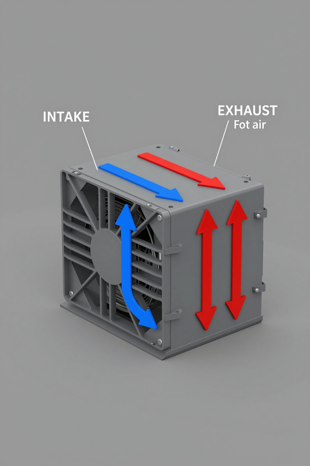
- Thermal: The condenser is the heart of the heat rejection system. The thermal design of the entire enclosure should be built around providing it with a clear path for cool intake air and a separate path for hot exhaust air to prevent recirculation. The system is rated to operate up to 55°C, but providing it with cooler intake air will always improve efficiency and reduce power consumption.
- Maintenance: The most critical maintenance task is keeping the condenser fins clean. In dusty environments, this should be part of a weekly or even daily check. Periodically inspect electrical connections for tightness and wiring for any signs of abrasion, particularly in applications with high vibration or user movement.
Frequently Asked Questions (FAQ)
Why does my cooling system shut down on startup, even with a fully charged battery?
This is the classic symptom of insufficient peak current capability. Your battery’s management system (BMS) is likely detecting the 33A inrush current as a short circuit and cutting power to protect the cells. Your power source must be explicitly rated to handle this peak load.
The unit cools well for the first hour, then performance drops off. What’s the first thing to check?
Check the condenser airflow path immediately. This behavior is typical of heat soak caused by a blocked or restricted condenser. Look for dust or debris clogging the fins, or an object that has shifted and is now blocking the intake or exhaust.
Can I run this directly from a vehicle’s 12V accessory port?
It is highly unlikely to work reliably. Most accessory ports are fused at 10A or 15A, which is far below the 33A peak current required for compressor startup. The unit should be connected to a dedicated, high-amperage circuit with appropriate wiring and fusing.
How much of a factor is the 60 dBA noise level?
At 60 dBA, the noise is comparable to a normal conversation. However, its proximity to the user’s head and the nature of the sound (a compressor and fan) can be a factor in some applications. Mounting the unit with vibration isolation can help prevent the noise from being amplified by the larger structure.
Is a thermoelectric (Peltier) system a better choice to avoid these power spikes?
A thermoelectric system does avoid the inrush current problem, which simplifies the electrical design. However, it comes at the cost of lower efficiency, especially in the high ambient temperatures where personal cooling is most needed. This means it may draw more average power and require a larger battery for the same amount of cooling over a full shift.
What is the most overlooked aspect when sizing the power system for a micro dc aircon for cooling suit use?
Voltage drop over the length of the power cable. Engineers often size the power source correctly but use a wire gauge that is too small for the distance. During the 33A peak draw, the voltage drop across an undersized wire can cause the voltage at the unit’s terminals to fall below its operational threshold, leading to startup failure.
The unit weighs 2.2 kg. How does that impact a wearable design?
In a wearable system, every kilogram matters. The 2.2 kg mass of the cooling unit must be a primary consideration in the ergonomic design of the garment or pack. The load must be distributed comfortably to avoid user fatigue over a long period of use.
Conclusion: It’s a Power Systems Problem First
Successfully integrating a micro dc aircon for cooling suit systems hinges on treating it as a power electronics challenge before you even begin the thermal calculations. The most common field failures are not due to a lack of cooling capacity, but a failure to design for the dynamic electrical loads of a micro-compressor.
By focusing on the peak current demand, ensuring stable voltage under load, and planning for real-world environmental conditions, you can design a system that delivers on the promise of sustained cooling. When the application demands high-performance cooling in a compact, DC-powered form factor, a vapor-compression system is often the most effective approach, provided these integration principles are followed.
If your project requires this level of thermal performance, you can find more details on our solutions here: AlphaCooler Micro DC Air Conditioner.


0 条评论