Field Snapshot: The Limits of Air Cooling in the active cooling vs fan cooling for UAV platforms Debate
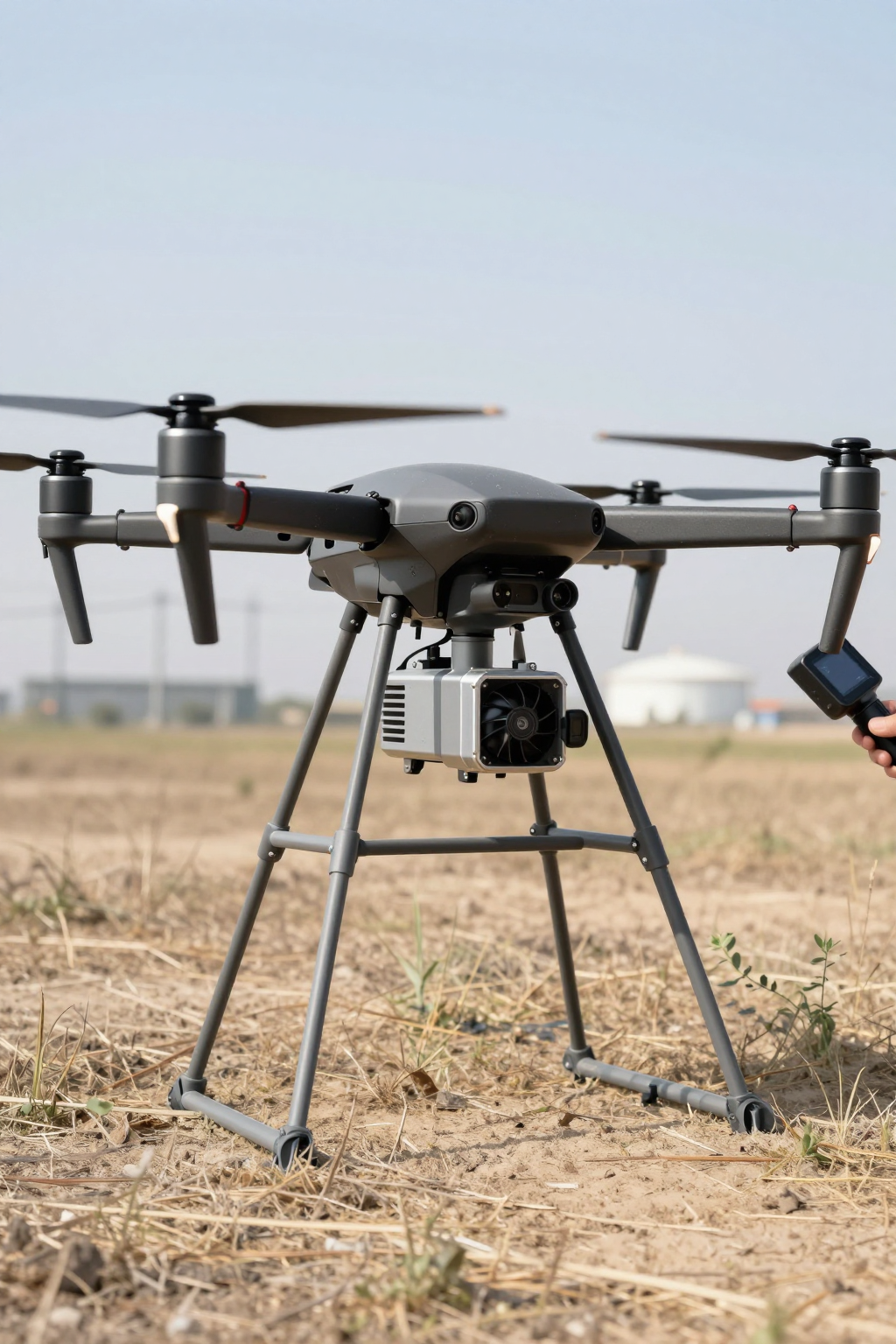
We recently worked with a UAV integration team facing a persistent issue: their high-resolution sensor payload was overheating during stationary hover operations. On the ground and during forward flight, everything looked fine. But once the platform was held in a fixed position for surveillance, the sensor data would begin to drift, eventually forcing a mission abort. Their existing cooling system, a set of high-flow fans and heatsinks, was proving ineffective precisely when the mission-critical data was being gathered. The core problem was twofold: the drone lost the benefit of forward airspeed, and ambient air temperatures on site were higher than anticipated.
This scenario is a classic inflection point in mobile system design. It marks the boundary where passive and simple forced-air cooling methods reach their physical limits. The team’s challenge wasn’t a faulty fan; it was a fundamental mismatch between the cooling strategy and the operational environment. By the end of this post, you’ll be able to identify the key decision gates that signal when a shift from air cooling to an active, below-ambient thermal solution is necessary for your own mobile platform.
Initial Thermal Diagnostics: What We Check First
Before recommending a system redesign, our first step is always to validate the performance and constraints of the existing setup. In situations like this, we work through a quick diagnostic checklist to confirm the root cause. This isn’t about finding a broken part; it’s about defining the boundaries of the current system’s capability.
- Check: Airflow Path Integrity. We first inspect the physical setup. Are fans, heatsinks, and vents free of obstruction? Is air being ducted effectively from an intake, across the heat source, and out an exhaust? Is there any possibility the system is just recirculating its own hot exhaust air?
- Why: An obstructed or poorly designed airflow path is a common and easily correctable issue. It’s the first thing to rule out before considering more complex solutions.
- What it suggests: If the paths are clear and the design seems sound, but the payload is still overheating, it strongly suggests the cooling system’s fundamental capacity is being exceeded. The system is doing its job, but its best isn’t good enough.
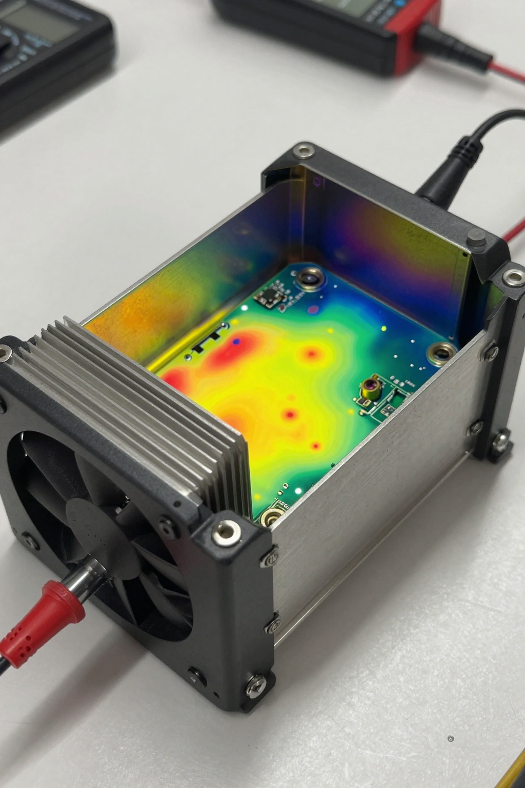
- Check: Ambient vs. Payload Temperature Differential. We log the ambient air temperature and compare it to the temperature of the payload’s case or heatsink during operation.
- Why: All fan-based cooling systems rely on this temperature difference (ΔT). Heat will only move from the hotter object to the cooler air. If the ambient air is already hot, the fan has very little thermal potential to work with.
- What it suggests: A small differential, especially on warm days, indicates the fan is just circulating hot air. This is a clear sign that any solution dependent on ambient air will struggle. The problem is no longer about airflow volume; it’s about the temperature of that air.
- Check: Operational State vs. Temperature. We correlate the temperature logs with the UAV’s flight controller logs. When, specifically, do the temperature spikes occur?
- Why: This pinpoints the exact operational trigger for the thermal failure. Is it during high-power processing, data transmission, or, as in this case, a specific flight maneuver like hovering?
- What it suggests: If overheating is tightly coupled with static or low-speed states, the system’s dependency on forward airspeed for convection is the primary failure point. The cooling solution that works at cruise speed is inadequate for stationary tasks.
Common Failure Modes for UAV Fan Cooling
The diagnostics often reveal a pattern. Fan-based systems, while simple and lightweight, are subject to environmental and operational constraints that can lead to mission failure. Recognizing these failure modes is key to understanding the debate around active cooling vs fan cooling for UAV platforms.
- Symptom: Sensor data drifts or the payload shuts down during hover.
Likely Cause: Complete loss of forced convection from forward flight. The fans alone cannot generate enough localized airflow to compensate for the heat buildup.
Why it matters: This disqualifies the platform from any mission requiring stationary observation, such as infrastructure inspection, persistent surveillance, or precise LiDAR mapping. - Symptom: Cooling performance degrades significantly on hot days.
Likely Cause: The ambient air temperature is too close to the payload’s maximum operating temperature, minimizing the effectiveness of the heatsink.
Why it matters: This severely limits the operational envelope of the UAV, making it unreliable in certain climates or seasons and reducing deployment readiness. - Symptom: The payload’s processor throttles under heavy load, even in cool weather.
Likely Cause: The existing fan and heatsink assembly cannot dissipate the peak heat flux generated by the electronics.
Why it matters: The full processing capability of an expensive payload cannot be utilized, effectively wasting investment and limiting the platform’s performance. - Symptom: Frequent maintenance is required to clear clogged heatsink fins.
Likely Cause: Forced-air systems are open to the environment, continuously pulling in dust, moisture, and debris.
Why it matters: This increases operational overhead, reduces reliability, and creates a risk of sudden thermal failure in the field if a blockage occurs mid-mission.
Decision Gates: When to Move to Active Cooling
Moving to an active cooling solution is an engineering trade-off. It adds capability but also introduces new integration considerations. The decision should be driven by clear, mission-defined constraints. Here are the three most common gates that force the transition.
Gate 1: The Ambient Temperature Constraint
- Constraint: The mission requires reliable operation in high ambient temperatures that are at or near the payload’s maximum allowable temperature.
- Decision Trigger: When the temperature differential between the environment and the target component temperature is too small for a fan to be effective, a different approach is needed.
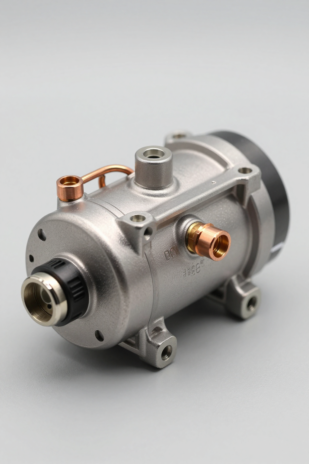
- Engineering Resolution: Implement a system that can create its own temperature differential by actively chilling a surface below the ambient temperature. Vapor-compression refrigeration is a common technology for this, as it physically moves heat energy against the thermal gradient.
- Integration Trade-off: This resolution introduces a powered component (the compressor) that adds weight and consumes more power than a simple fan, impacting flight endurance.
Gate 2: The Static Operation Constraint
- Constraint: The mission profile includes extended periods of stationary hover or low-speed flight where external airflow is negligible.
- Decision Trigger: The payload cannot maintain its required operating temperature without the aid of significant external airflow from forward motion.
- Engineering Resolution: A closed-loop cooling system is required. In a miniature vapor-compression system, the evaporator is directly coupled to the payload (often via a cold plate), and the condenser (the ‘hot side’) is placed elsewhere to reject heat. The payload cooling becomes independent of external airflow.
- Integration Trade-off: This adds mechanical complexity. The system requires refrigerant lines, a compressor, and a condenser, all of which must be packaged within the UAV’s space and weight budget.
Gate 3: The Payload Stability Constraint
- Constraint: The payload—such as a LiDAR sensor, high-resolution camera, or frequency-sensitive radio—requires a highly stable temperature to prevent data drift, calibration loss, or signal noise.
- Decision Trigger: Passive or fan-based systems result in wide temperature swings that correlate with processing load and ambient conditions, violating the payload’s stability requirements.
- Engineering Resolution: An active, thermostatically controlled system can maintain a specific temperature setpoint with much greater precision. A vapor-compression system can be cycled on and off by a controller to hold a payload within a very narrow temperature window.
- Integration Trade-off: This requires more sophisticated control logic and sensors. The power system must also be able to handle the cyclic load of the compressor starting and stopping.
Integration Notes for Miniature Vapor-Compression Systems
Integrating a miniature active cooling system is a component-level task, not a drop-in replacement for a fan. It requires a holistic approach to system design. These are not procedural steps but rather key areas of consideration we’ve learned from field deployments.
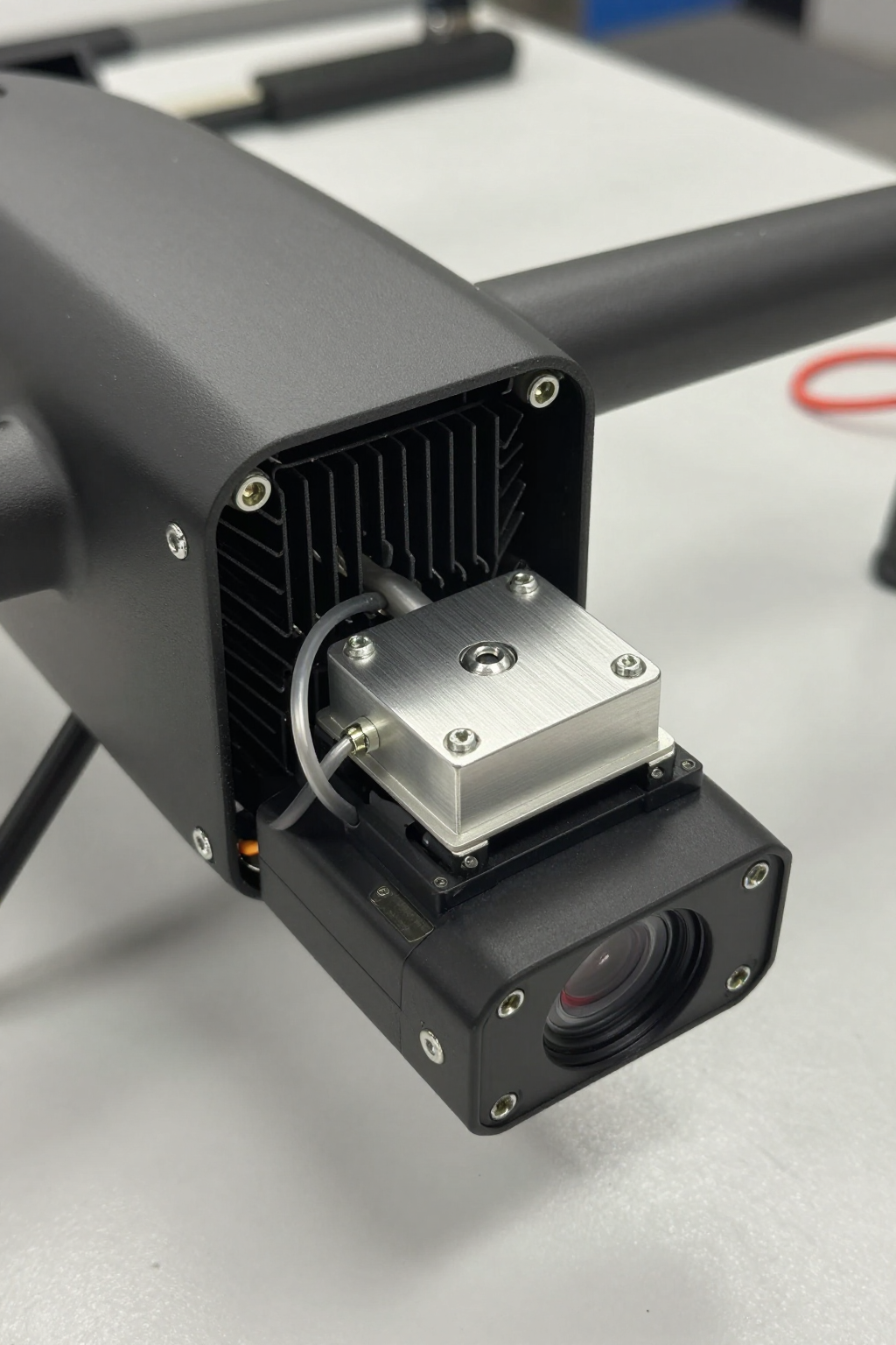
- Mechanical: The miniature rotary compressor, while small, does generate vibration. It’s critical to use appropriate damping mounts to isolate it from the airframe and especially from vibration-sensitive payloads like cameras or IMUs. Component layout must be planned carefully; the condenser needs access to some airflow (even from a small, dedicated fan) to dissipate rejected heat effectively.
- Electrical: The power budget is a primary design constraint. The system requires a stable DC power source, and the inrush current during compressor startup must be accounted for in the power distribution network to avoid voltage sags that could affect other subsystems. Shielding of power lines may be needed to mitigate potential EMI.
- Thermal: An active system is not magic. A robust thermal pathway must be engineered to move heat from the payload to the system’s evaporator. This is often accomplished with a custom-machined cold plate. Likewise, the waste heat from the condenser must be managed and exhausted away from the payload and other sensitive electronics to prevent secondary heating.
- Maintenance: Unlike fans that can be easily replaced, these are typically sealed refrigerant systems. Field service is generally not practical. Reliability is high, but the integration plan should treat it as a line-replaceable unit. Maintenance focuses on ensuring electrical connections are secure and that the condenser fins remain clear of debris.
Frequently Asked Questions from the Field
When teams first consider moving beyond fans, the same practical objections and questions tend to arise. Here are some of the most common ones we address.
Isn’t adding a compressor and its components too heavy for our UAV?
It’s a definite trade-off. However, the weight of an active system must be compared against the weight of an increasingly large and ineffective heatsink and fan assembly. In many cases, the mission is simply not possible without active cooling, making the weight a necessary addition to achieve the required capability.
What about the power draw? Our flight time is already a major constraint.
Power consumption is a critical budget item. An active cooling solution is typically specified for missions where thermal limits are the primary bottleneck, not endurance. The power draw, which is often managed by cycling the compressor, must be factored into the overall mission profile and endurance calculations from the start.
Why can’t we just use a bigger, more powerful fan?
A bigger fan cannot solve the core thermodynamic problem. If the ambient air is too hot, even infinite airflow won’t cool the component below that ambient temperature. A more powerful fan also has diminishing returns in a cluttered enclosure and can’t overcome the lack of airflow during a stationary hover.
We looked at thermoelectric (Peltier) coolers. How is this different?
Thermoelectric coolers are solid-state, which is appealing. However, vapor-compression systems are generally more efficient (have a higher Coefficient of Performance), especially as the heat load increases. A key challenge with Peltier devices is that they generate significant waste heat on their ‘hot side,’ which can create a new, more difficult thermal problem to solve within a compact airframe.
Can this type of system cool the entire drone electronics bay?
It’s not typically used for that. Miniature vapor-compression systems are engineered for high-heat-flux spot cooling. Their strength is in pulling a large amount of heat from a small, critical area—like a processor or sensor—rather than lowering the temperature of a large volume of air.
How does an active system handle dust and moisture in the field?
The refrigerant loop itself is a hermetically sealed system, making it very resilient. However, the condenser, which acts as the system’s radiator, still needs to reject heat to the atmosphere. Care must be taken to keep its fins clear of debris to maintain efficiency, much like any heat exchanger.
Conclusion: Matching the Tool to the Thermal Problem
For UAV platforms operating in moderate climates with mission profiles that ensure constant forward flight, a well-designed forced-air cooling system is often a simple, reliable, and lightweight solution. It’s an appropriate tool for a well-defined job.
However, as performance demands grow, the conversation around active cooling vs fan cooling for UAV platforms becomes unavoidable. When missions require stationary operation in place, performance in high ambient temperatures, or precise thermal stability for sensitive payloads, the physical limitations of fan cooling become the primary barrier to success. In these scenarios, an active cooling system is not an over-engineered luxury; it is a direct enabler of the core mission capability. It addresses the fundamental constraint that air cooling cannot: the inability to cool below the ambient temperature.
For engineering teams designing systems that are pushing up against these thermal boundaries, a component-level approach is often the next step. A miniature DC compressor provides the core technology to build a targeted, high-performance active cooling solution.


0 条评论