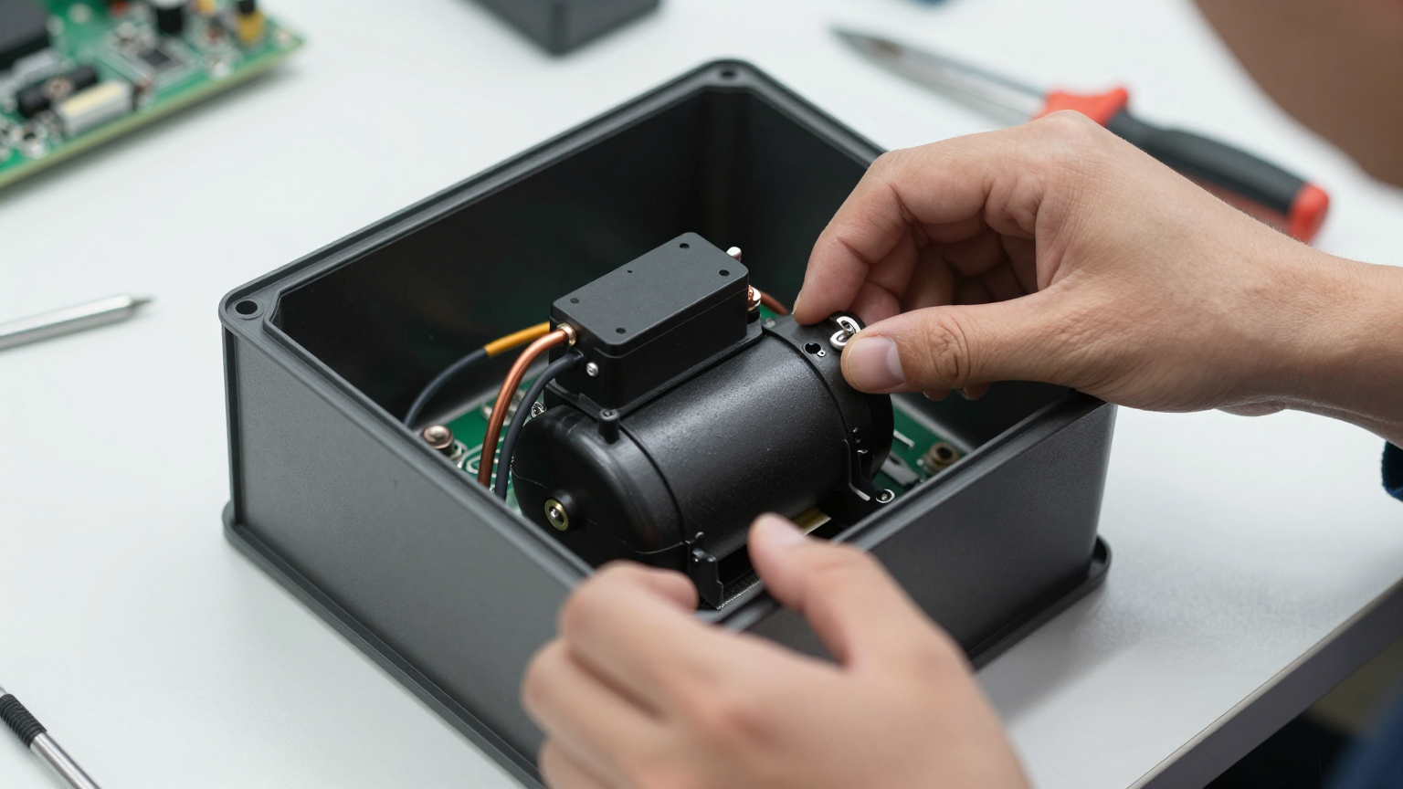
We were on-site with a client developing a portable analytical instrument. The issue wasn’t catastrophic failure, but something more subtle: a rising number of field returns with notes like “results inconsistent” or “calibration drift.” The devices worked fine on the bench, but in the field, performance became unreliable. This is a classic failure chain for battery-powered systems: unmanaged thermal loads lead to temperature instability, which causes performance drift, and ultimately, costly RMAs. This post documents the decision process for integrating active, high-precision cooling to solve this exact problem.
By the end of these notes, you’ll have a clear framework for identifying the constraints that push a design beyond passive or thermoelectric cooling and require a miniature, variable-speed DC compressor.
Field Snapshot: Sizing a battery powered compressor cooling system
The core challenge with any battery-powered device is the trade-off between performance, runtime, and physical constraints. Adding a thermal management subsystem adds another layer of complexity. Before specifying any hardware, we start with a few fundamental checks to define the boundaries of the problem. Skipping these often leads to selecting a component that solves the wrong problem.
First System Checks
Before evaluating cooling hardware, we establish the baseline operating conditions. These initial data points often narrow the field of viable solutions significantly.
- Check: Map the complete thermal load profile, especially peak vs. average load.
Why: Many systems are sized for an average heat load, leading to thermal runaway when the device operates at peak performance for an extended period.
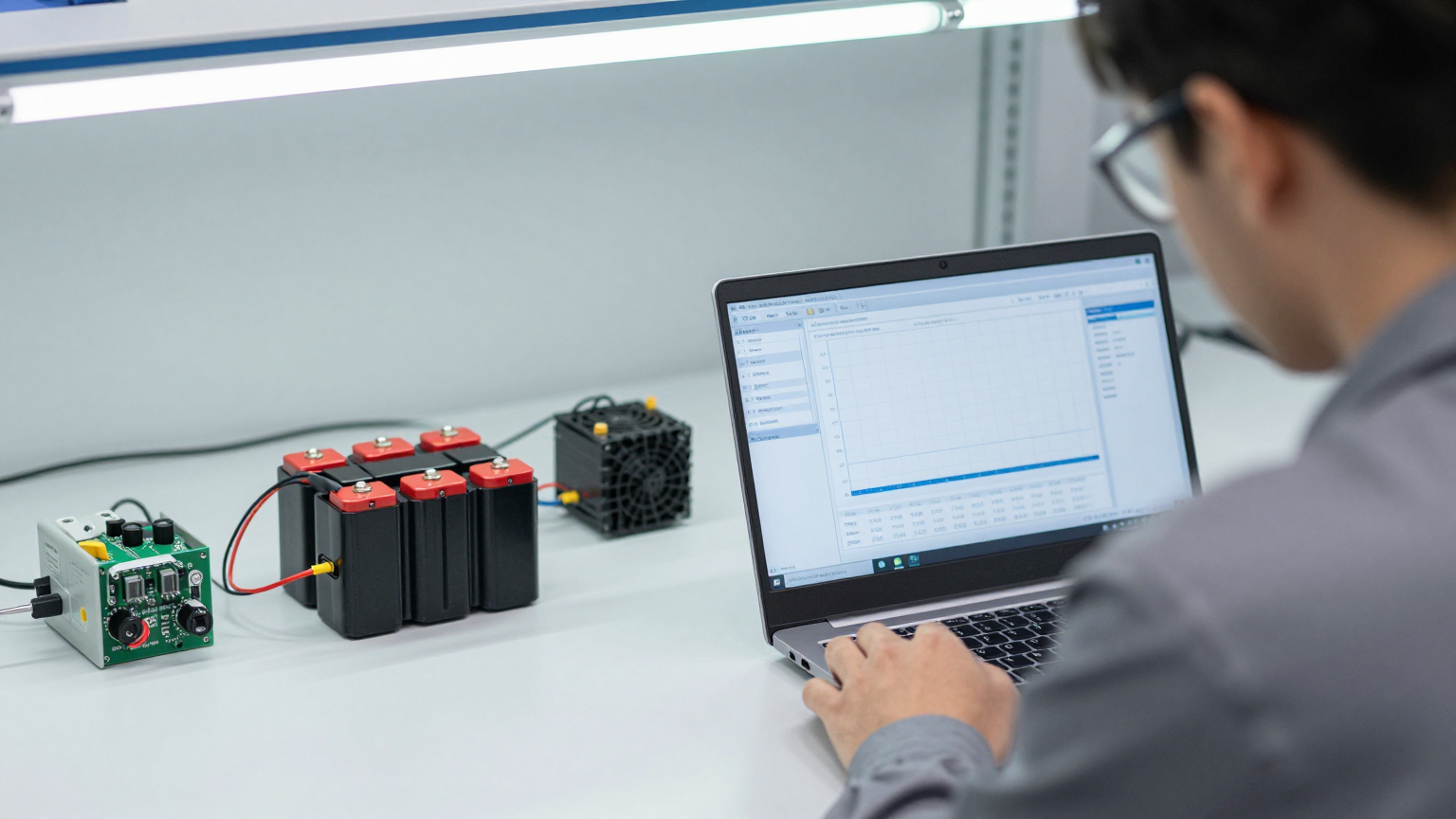
What it suggests: A large gap between average and peak load indicates that a simple passive solution is unlikely to be sufficient. It points toward a system that can respond dynamically to load changes. - Check: Characterize the battery’s voltage curve under load, specifically during system startup.
Why: The inrush current of a motor can cause significant voltage sag, especially with long wire runs or batteries with high internal resistance.
What it suggests: If voltage drops significantly, the power delivery system may be inadequate for any active cooling system. This must be addressed at the source before adding a compressor, which has its own startup current demands. - Check: Define the absolute maximum ambient operating temperature.
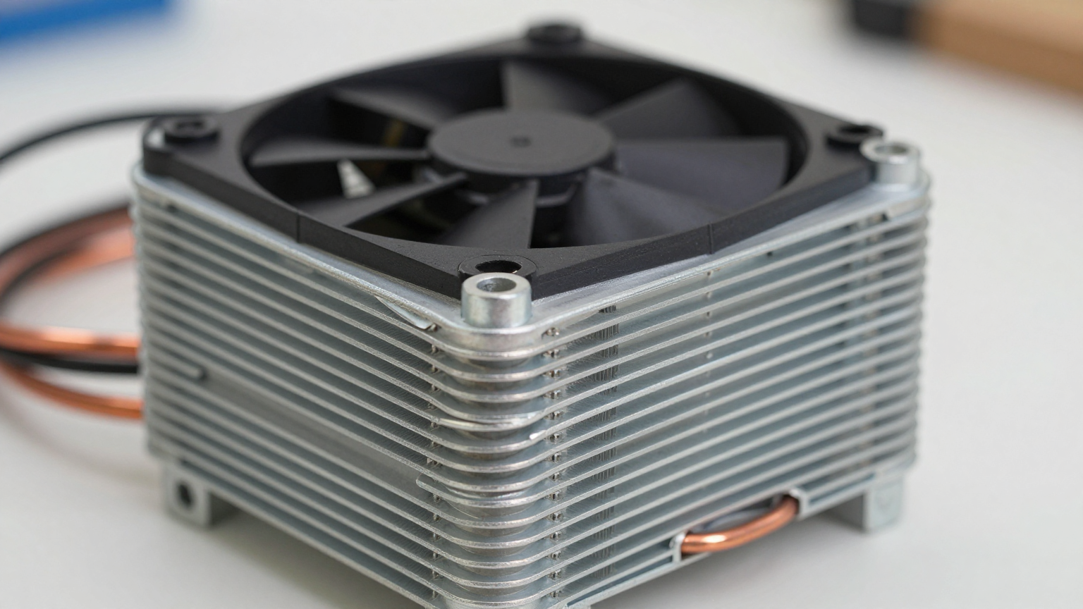
Why: Passive solutions (heat sinks) and, to a lesser extent, thermoelectric coolers (TECs) have their performance directly tied to the ambient temperature. They can only move heat, not cool below the surrounding temperature.
What it suggests: If the required internal temperature of your enclosure is near or below the maximum external ambient temperature (up to 55°C in some field conditions), passive cooling is not a viable path.
Common Failure Modes & Constraints
When a battery-powered cooling system fails in the field, it’s often due to one of these underlying issues. Understanding them helps in designing a more robust system from the start.
- Symptom: The system never reaches the target temperature, especially when the device is working hard.
Likely Cause: An underpowered compressor. The cooling capacity was likely sized based on average power dissipation, not the peak thermal load generated by the electronics. - Symptom: The compressor controller faults on startup, or the entire device resets.
Likely Cause: Voltage sag. The battery and/or power wiring cannot supply the necessary startup current without the voltage dropping below the controller’s operational threshold. - Symptom: Cooling performance is strong initially but degrades quickly as the system runs.
Likely Cause: Inadequate condenser cooling. The heat removed from the electronics, plus the heat generated by the compressor itself, is not being effectively exhausted from the system. This is a very common integration challenge. - Symptom: A gradual, steady decline in cooling capacity over weeks or months.
Likely Cause: A slow refrigerant leak. This is often traced back to joint stress caused by vibration or improper brazing during assembly. - Symptom: The compressor runs erratically or fails to follow its speed command.
Likely Cause: A mismatched controller. The driver board’s firmware and electrical characteristics must be precisely matched to the specific miniature DC compressor model being used.
Decision Gates for Active Cooling
At several points in the design process, you’ll face a decision: stay with a simpler solution or move to a more capable one. Here are the common gates that lead engineers to a miniature compressor-based system.
Gate 1: The Sub-Ambient Requirement
- Constraint: The temperature of the critical component (e.g., a sensor, laser, or processor) must be maintained below the maximum possible ambient temperature.
- Decision Trigger: As soon as `T_required < T_ambient_max`, all passive heat sink solutions are disqualified. The system must be capable of active refrigeration.
- Engineering Resolution: The choice becomes between a thermoelectric cooler (TEC) and a vapor-compression system.
- Integration Trade-off: Moving to active cooling immediately introduces a significant power draw and increases system complexity. The question is no longer *if* you need active cooling, but *which type* is most effective.
Gate 2: The Heat Flux Barrier
- Constraint: The system generates a high thermal load (e.g., 100W to 550W) or has a high heat flux (heat per unit area).
- Decision Trigger: Thermoelectric coolers become progressively inefficient as the heat load and the temperature differential (ΔT) increase. To handle a high heat load, a TEC assembly would become large, heavy, and consume a prohibitive amount of power.
- Engineering Resolution: A miniature DC compressor system is often selected. Its vapor-compression cycle is significantly more efficient at moving larger amounts of heat.
- Integration Trade-off: While more efficient, a compressor system introduces mechanical components (the compressor itself) and requires a closed refrigerant loop with a condenser and evaporator, making the initial integration more complex than a solid-state TEC.
Gate 3: The Battery Life Imperative
- Constraint: The device must operate for a target duration on a single battery charge.
- Decision Trigger: A TEC-based solution, due to its lower Coefficient of Performance (COP), consumes too much of the power budget, resulting in inadequate battery life.
- Engineering Resolution: A variable-speed DC compressor is chosen for its higher COP. It performs more cooling work per watt of electricity consumed, directly extending the operational runtime of the device.
- Integration Trade-off: The system must now accommodate the compressor’s physical volume and weight (around 750g for the compressor alone), plus the associated heat exchangers. The power delivery system also needs to handle the compressor’s specific startup and running current profiles.
Integration Notes
Successfully integrating a miniature DC compressor requires thinking beyond the component itself. It’s about how it interacts with the entire system.
- Mechanical: The compact size is an advantage, but it’s not a simple drop-in. The unit produces some vibration, so mounting points may need dampening, especially if the device includes sensitive optics or sensors. Plan the routing of refrigerant lines carefully to avoid sharp bends and stress on the joints.
- Electrical: A stable power source is critical. These compressors are available in various DC voltages (typically 12V, 24V, or 48V). Use appropriately gauged wiring to minimize voltage drop between the battery, controller, and compressor. The variable-speed control is a key feature for efficiency and thermal stability; ensure the controller is properly matched and configured.
- Thermal: This is the most common point of failure. You must manage two thermal paths. The evaporator absorbs heat from your device. The condenser must then reject that heat, *plus* the waste heat from the compressor motor, into the ambient environment. Providing a clear, unobstructed airflow path for the condenser is non-negotiable. Starving the condenser of air will cause high-side pressure to rise and cooling performance to collapse.
- Maintenance: The compressor and refrigerant loop (using R134a) are a sealed, closed-loop system. In many deployments, this requires minimal maintenance. The primary task is ensuring that the condenser and any associated fans remain free of dust and debris that could impede airflow.
Frequently Asked Questions
- What’s the biggest mistake when sizing a battery powered compressor cooling system?
Sizing for the average thermal load instead of the peak. A system that can’t handle the peak load will allow the component temperature to drift, which is often the very problem you’re trying to solve. - How is this a better choice than a Peltier (TEC) cooler?
It depends on the heat load. For very low heat loads, a TEC can be simpler. But as the amount of heat to be moved increases, the compressor system’s superior Coefficient of Performance means it uses far less battery power to achieve the same amount of cooling. - Can I run this directly from a small LiPo battery pack?
It depends on the battery’s discharge rating and internal resistance. The compressor’s startup current can cause a voltage sag that trips the controller’s undervoltage protection. The power source must be robust enough to handle this inrush current without collapsing. - How much space does the full system require?
While the compressor itself is small (a typical unit weighs around 750g), you must also budget space for a condenser, an evaporator (cold plate), and potentially fans for airflow. The total volume depends heavily on the total heat rejection requirement. - Can this system operate in a hot desert environment?
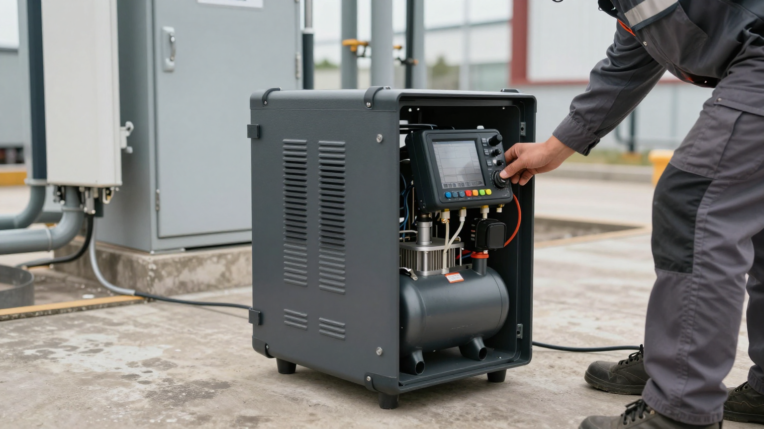
Yes, these systems are often designed for high ambient temperatures. Many can operate effectively in ambient conditions up to 55°C, which is a key advantage over passive or less efficient active coolers. - Is the variable-speed feature really necessary?
For achieving high-precision thermal stability, yes. It allows the system to precisely match the cooling rate to the thermal load, avoiding the temperature oscillations that occur with simple on/off control. This also improves overall energy efficiency.
Conclusion: When to Make the Switch
Moving to a miniature DC compressor is a significant design decision. It’s often the right path when your battery-powered device must deliver consistent performance regardless of peak processing loads or high ambient temperatures. If passive solutions can’t keep you below ambient, and thermoelectric coolers are too inefficient to meet your battery life targets, a battery powered compressor cooling system provides the high-performance, high-efficiency solution needed to prevent thermal drift and ensure reliability in the field.
When you need to explore the specific capabilities of these compact systems, the technical specifications are the best place to start. You can review the performance curves and integration requirements for our range of miniature DC compressors to see if they fit your design envelope.


0 条评论