Field Snapshot: The Challenge of Scaling Battery Cooling from Module Level to Pack Level
We see it often in the field. An engineering team develops a cooling system for a single battery module. In the lab, it works beautifully. The prototype holds the target temperature with a small, efficient active cooling loop. The project gets the green light. The next step is to build the full pack, often by simply multiplying the single-module design by the number of modules. Then comes the first high-load test. Within minutes, temperatures across the pack climb past their limits, the system throttles, and the test is a failure. The linear scaling approach that seemed so logical has completely broken down.
This scenario is a common and costly roadblock. The physics of thermal management do not scale linearly. The transition from a controlled, single-module environment to a dense, high-power battery pack introduces complex variables that can overwhelm an undersized or poorly integrated system. This is where a methodical approach to sizing becomes critical.
These field notes are for the engineer facing this exact problem. We will walk through the diagnostic checks, failure modes, and critical decision gates for properly scaling battery cooling from module level to pack level. By the end, you will have a clear framework for evaluating the total thermal load and selecting the right components for a robust, reliable active cooling solution.

Initial Diagnostic Checks: Where Linear Scaling Fails
When a scaled-up system underperforms, the root cause is rarely a single faulty component. It’s typically a series of flawed assumptions made during the transition from module to pack. Before redesigning the system, we start with these foundational checks.
- Check: Total Heat Load Calculation.
Why: A full battery pack’s heat load is not just the sum of its modules. It also includes significant heat generated by busbars, contactors, and the Battery Management System (BMS) itself, especially under high current. Simple multiplication ignores these auxiliary sources.
What it suggests: The actual peak heat load is likely much higher than the initial estimate. A comprehensive thermal model should account for all heat-generating components within the enclosure. - Check: Thermal Pathways and Interface Resistance.
Why: Stacking modules together fundamentally changes the thermal landscape. Air gaps between modules can act as insulators, while contact points can create thermal bridges. The path from the cell core to the cold plate becomes longer and more complex.
What it suggests: The original cold plate design, which was effective for one module, may now be a bottleneck, creating uneven temperature distribution and hot spots across the pack. - Check: Internal Enclosure Ambient Temperature.
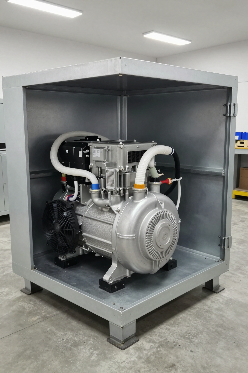
Why: A single module is often tested on an open bench, where it rejects heat into the entire room. A full pack is sealed in an enclosure. The heat rejected by the batteries, electronics, and the cooling system’s own components (like the condenser) raises the internal ambient temperature significantly.
What it suggests: The cooling system isn’t fighting the external ambient temperature; it’s fighting a much higher local ambient temperature inside the box. This severely reduces the condenser’s ability to reject heat, crippling the entire system’s performance.
Common Failure Modes and System Constraints
When a battery thermal management system is undersized, it manifests in predictable ways. Recognizing these symptoms helps pinpoint the specific constraints that were overlooked during the scaling process.
- Symptom: Rapid Temperature Rise During Fast Charging.
Likely Cause: The peak heat load during charging exceeds the system’s real-time cooling capacity. The compressor and heat exchangers cannot remove energy as fast as it is being generated.
Why it Matters: This is the most dangerous failure mode. Exceeding cell temperature limits, even for short periods, accelerates chemical degradation, reduces cycle life, and in worst-case scenarios, can increase the risk of thermal runaway. - Symptom: Compressor Runs Continuously at Max Speed.
Likely Cause: The system is thermally saturated. It’s running at 100% capacity but cannot achieve the temperature setpoint. This could be an undersized compressor or, more commonly, an undersized condenser that cannot reject the collected heat.
Why it Matters: This indicates a system operating at its absolute limit. It leads to excessive power consumption, premature wear on the compressor, and provides no safety margin for hotter days or higher loads. - Symptom: Wide Temperature Variance Across the Pack.
Likely Cause: Inadequate or unbalanced coolant flow. When scaling to multiple cold plates in parallel, without proper hydraulic design, some modules will receive less coolant flow than others.
Why it Matters: Cell imbalance is a primary driver of pack degradation. Modules that run hotter will age faster, leading to a reduction in the entire pack’s usable capacity and lifespan. - Symptom: System Fails on Hot Days.
Likely Cause: The heat rejection system (condenser and fan) was sized for nominal, not worst-case, ambient conditions. A vapor-compression system’s performance is directly tied to its ability to dump heat into the environment.
Why it Matters: A system that isn’t designed for the maximum specified ambient temperature (e.g., 52°C) is not commercially viable. Performance must be predictable across the entire operational range. - Symptom: Unexpected System Shutdowns.
Likely Cause: The compressor’s external controller is triggering a protection fault. This is often due to over-temperature or over-current conditions caused by the system being forced to operate far outside its designed parameters, such as trying to run with a condensing temperature above its 65°C limit.
Why it Matters: This means a total loss of cooling. If this happens under load, it can lead to catastrophic battery damage. It’s a clear sign the system is fundamentally undersized.
Decision Gates for Sizing an Active Cooling System
Properly scaling battery cooling from module level to pack level requires moving through a series of engineering decision gates. Each gate forces a deliberate choice based on the system’s constraints.
Gate 1: Is Passive or Forced-Air Cooling Sufficient?
- Constraint: The battery pack must operate at or below ambient temperature, or its peak heat load under fast charge/discharge is too high for simple heat sinks and fans to dissipate within the enclosure’s volume.
- Decision Trigger: Thermal modeling shows that even with high-performance fans, internal cell temperatures will exceed their optimal range on a hot day.
- Engineering Resolution: Transition to an active refrigeration technology. Unlike passive methods, a vapor-compression system can actively pump heat out of the enclosure and achieve temperatures below the local ambient.
- Integration Trade-off: Active systems introduce higher complexity, power draw, and component cost compared to passive or forced-air solutions. However, they are often the only way to meet the performance and longevity requirements of high-density battery packs.
Gate 2: Is a Simple On/Off System Adequate?
- Constraint: The battery’s thermal load is highly dynamic (e.g., robotics, delivery vehicles), and maintaining a very stable temperature is critical for predictable performance and maximizing cell life.
- Decision Trigger: Simple on/off control of the compressor leads to significant temperature cycling around the setpoint. This thermal stress can be detrimental to battery chemistry over time.
- Engineering Resolution: Implement a variable-speed compressor system. Using a PWM or 0-5V analog signal from the BMS, the compressor’s speed can be modulated to precisely match the cooling demand in real time.
- Integration Trade-off: This requires a more sophisticated control loop integrated with the BMS. The benefit is superior temperature stability and much higher electrical efficiency, as the compressor only runs as hard as necessary.
Gate 3: How Do You Size the Compressor’s Capacity?
- Constraint: The compressor must be sized to handle the peak thermal load, not the average. This includes internal resistive heating, electrochemical inefficiencies, and external heat soak from the environment (e.g., solar loading).
- Decision Trigger: Worst-case analysis shows a total heat load that approaches or exceeds the capacity of smaller cooling solutions. For example, a pack generating 800-900 watts during a fast charge cycle.
- Engineering Resolution: Select a compressor with sufficient capacity at the expected operating conditions. A miniature DC compressor with a capacity of up to 900W (at HBP conditions) can provide the necessary headroom for demanding pack-level applications.
- Integration Trade-off: Sizing for peak load means the system might seem oversized for idle conditions. Variable-speed control is the key to mitigating this, allowing the powerful compressor to ramp down to very low power draw when the load is light.
Integration Notes for Pack-Level Deployments
Successful integration goes beyond just selecting the right compressor. The entire system must work in harmony. These are not step-by-step instructions but rather a collection of field observations for system integrators.
Mechanical
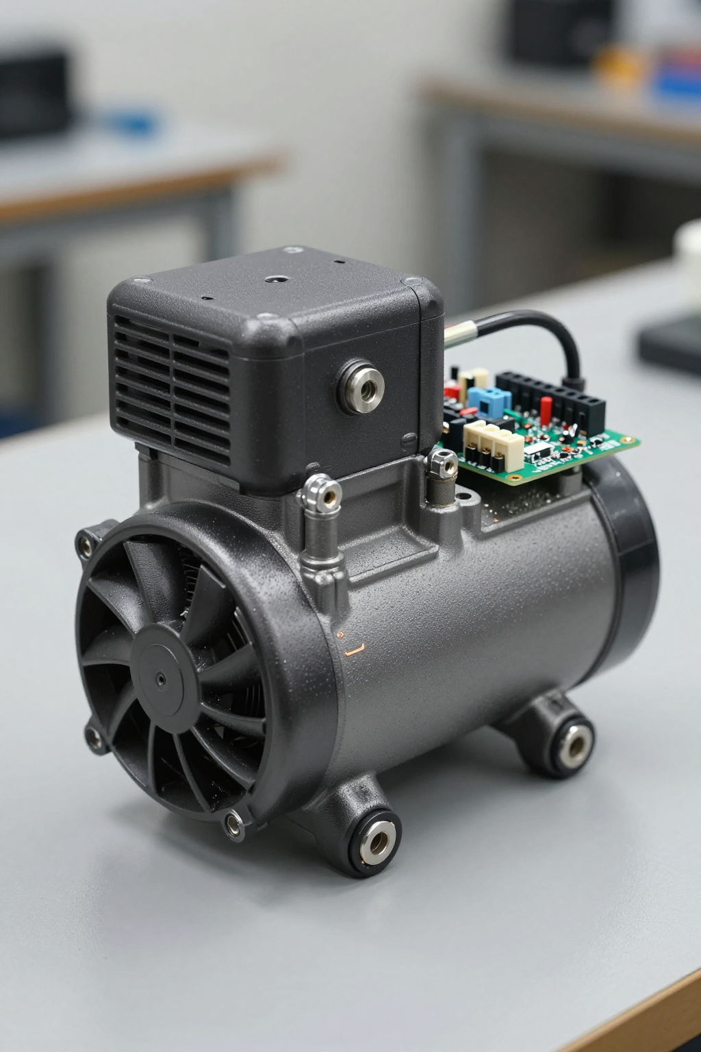
- Orientation: Most miniature DC compressors, including this one, are designed for vertical mounting to ensure proper oil management within the system. Deviating from this can impact long-term reliability.
- Vibration: While modern units have a low vibration design, consider using isolation grommets or mounts, especially if the pack is installed in a vibration-sensitive environment or near operators.
- Mass: Account for the full system weight. The compressor itself is 2.2 kg, but you must add the mass of the condenser, evaporator, tubing, and refrigerant charge to the final weight budget.
Electrical
- Power Supply: The system requires a stable 48V DC power source. The supply must be rated to handle the compressor’s rated current (6.5A) without significant voltage drop, as this can affect controller performance.
- Control Integration: An external controller is required for operation. This controller must be connected to the system’s master controller or BMS to provide the variable speed command signal (PWM or analog). This is the brain of the thermal management system.
Thermal
- Refrigerant Management: The system uses R134a refrigerant and must be evacuated and charged by a technician experienced with vapor-compression refrigeration. An incorrect charge is a common cause of poor performance.
- Heat Rejection: Condenser placement is critical. Ensure it has an unobstructed source of cool air and that its hot exhaust air cannot be re-ingested by the fan. Every degree of re-ingested air reduces system capacity.
- Insulation: Insulate all cold-side plumbing (from the evaporator to the compressor inlet). This prevents condensation and, more importantly, stops parasitic heat gain from the warm enclosure environment, improving net cooling capacity.
Frequently Asked Questions (FAQ)
- How do I calculate the total heat load for a battery pack?
- A thorough calculation involves summing the internal resistive heating (I²R losses), heat from electrochemical inefficiencies (refer to cell manufacturer data), and external heat soak. Always model for the worst-case scenario, such as a fast charge cycle at the highest rated ambient temperature.
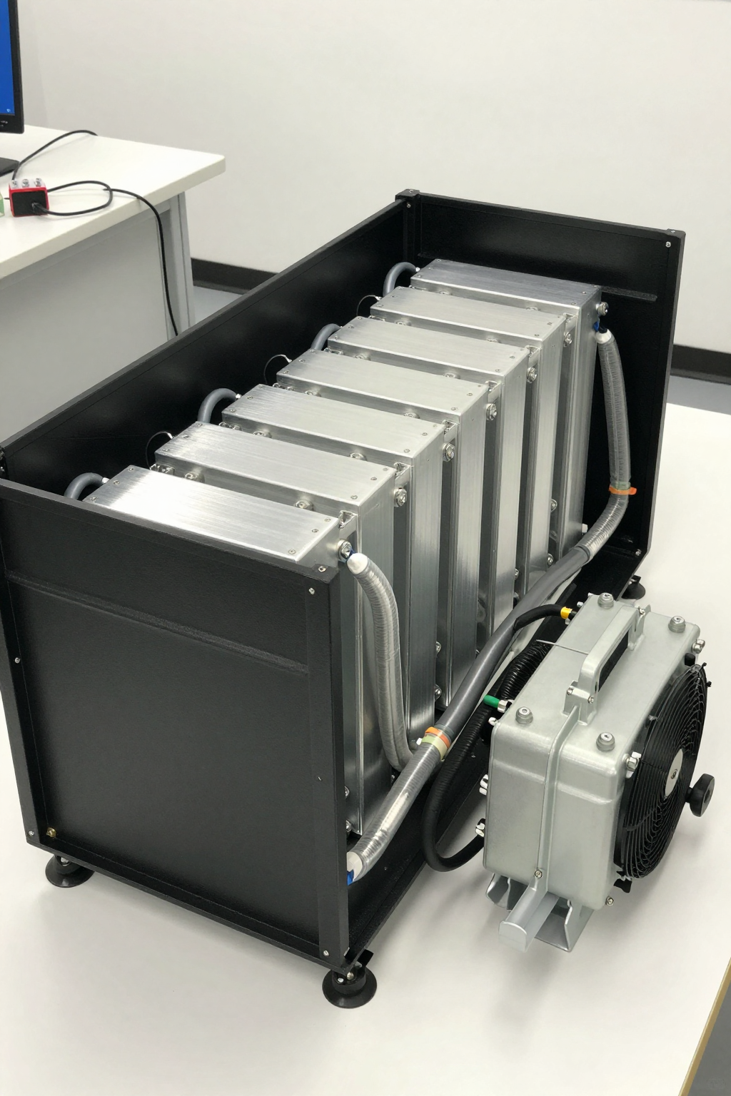
- Can I run multiple cooling plates from one compressor?
- Yes, this is a standard practice for pack-level cooling. However, it requires careful hydraulic design to balance the coolant flow across all parallel loops. Without proper balancing, some modules will be starved of coolant and overheat.
- What’s the efficiency difference between air and liquid cooling for batteries?
- Liquid cooling is substantially more effective for heat acquisition and transport in dense battery packs where airflow is restricted. An active liquid cooling system using a compressor takes this a step further, enabling sub-ambient cooling and much higher heat flux removal compared to a simple liquid-to-air radiator system.
- How does ambient temperature affect compressor performance?
- It has a critical impact. As the ambient temperature rises, the temperature difference between the condenser coil and the air decreases. This makes it harder for the system to reject heat, which in turn reduces the overall cooling capacity and increases the compressor’s power consumption.
- Is a 48V system powerful enough for a full automotive pack?
- It depends entirely on the pack’s heat load. For many applications in light EVs, autonomous mobile robots (AMRs), and stationary energy storage, a high-capacity 48V system is an excellent fit. For very large EV packs with extremely high C-rates, multiple units or a higher-voltage architecture may be required.
- What are the failure modes if the compressor is undersized?
- The primary failure is an inability to maintain the target temperature. The compressor will run constantly at maximum power, but the battery temperature will still climb under load, forcing the BMS to throttle performance and accelerating cell degradation.
Conclusion: When to Choose a Miniature DC Compressor System
The process of scaling battery cooling from module level to pack level reveals the limits of simple cooling methods. While an attractive option for early-stage prototypes, linear scaling of a module-level design is rarely robust enough for a final product.
An active cooling system built around a variable-speed miniature DC compressor is a strong engineering choice when the application demands performance that passive or forced-air solutions cannot deliver. This includes scenarios requiring operation in high ambient temperatures, the ability to cool below ambient, or the need for precise temperature control to maximize the battery’s performance and service life. For systems where above-ambient temperatures are acceptable and heat loads are very low, a simpler solution may be more cost-effective.
Ultimately, the decision rests on a thorough analysis of the pack’s total thermal load in its worst-case operating environment. For systems requiring robust, active thermal management, exploring the specifications of a high-capacity 48V miniature DC compressor is a logical next step.


0 条评论