Field Snapshot: Diagnosing an IVD Instrument Thermal Shutdown
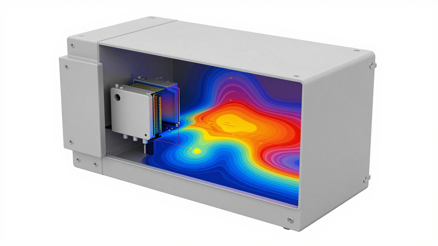
The scenario is a common one. An in-vitro diagnostic (IVD) analyzer, deployed in a point-of-care setting, operates as expected for the first couple of hours. Then, as its internal temperature gradually climbs, performance begins to derate. The system’s cooling fan is already at maximum speed, but it’s a losing battle. Air cooling can no longer suppress the heat buildup, leading to unstable temperatures for critical reagents and sensors. The result is a cascade of problems: compromised sample integrity, diagnostic delays, and costly reagent degradation. This isn’t just an inconvenience; it’s a fundamental reliability failure that undermines the instrument’s purpose.
When an instrument reaches this state, simply upgrading the fan is rarely the solution. The problem is often more systemic, rooted in the total thermal load exceeding the physical limits of air cooling. This field note walks through the diagnostic process for an IVD instrument thermal shutdown, moving from initial checks to the decision gates that determine when a system requires a fundamental shift from simple air cooling to active, compressor-based thermal management.
Initial Diagnostic Checks: Beyond the Obvious
Before concluding that the entire cooling architecture is insufficient, we start with a few fundamental checks. These steps help differentiate between a simple integration flaw and a core design limitation.
- Check: Airflow Pathways and Impedance.
Why: High-density component layouts, poorly routed cabling, or clogged vents can create significant impedance, preventing air from reaching critical hot spots. The fan might be working hard, but the air isn’t going where it’s needed.
What it suggests: If clearing pathways provides some relief but doesn’t solve thermal creep during long runs, the issue is likely heat density, not just airflow distribution. - Check: Ambient vs. Internal Temperature Differential.
Why: A large and persistent temperature difference between the enclosure’s interior and the surrounding room indicates the system is generating heat faster than it can be transferred out. The cooling system is saturated.
What it suggests: This points directly to the possibility that the total heat load exceeds the capabilities of air cooling, regardless of fan speed. The system has hit its convective thermal transfer limit. - Check: Thermal Interface Material (TIM) Integrity.
Why: Degraded or improperly applied TIM between heat sources (like processors or power modules) and their heat sinks creates a bottleneck. Heat can’t efficiently move from the component to the fins where air cooling can take over.
What it suggests: This can be a localized issue. However, if multiple components are running hot despite having dedicated heat sinks, it points back to a systemic problem where the enclosure’s internal ambient temperature is too high for any of the heat sinks to function effectively.
Common Failure Modes and System Constraints
When initial checks don’t resolve the issue, we look for patterns that reveal the underlying constraints of the thermal design. These symptoms often precede a full IVD instrument thermal shutdown.
- Symptom: Gradual temperature creep over long operational periods.
Likely Cause: Heat soak. The instrument’s chassis and all internal components slowly absorb thermal energy until they reach a saturation point. At this point, the air cooling system can only remove a fraction of the continuous heat being generated.
Why it matters: This confirms the problem is the total, continuous thermal load, not just transient peak spikes. The system lacks sufficient thermal headroom. - Symptom: Inconsistent reagent or sample temperatures.
Likely Cause: Localized hot spots near sensitive fluidic channels or reagent storage areas. Air cooling is non-specific and often cannot provide the precise, zonal cooling required for these functions.
Why it matters: It highlights the difference between general enclosure cooling and precision thermal stability. Air cooling addresses the former, but often fails at the latter. - Symptom: Fan speed is at maximum, but internal temperatures continue to rise.
Likely Cause: The air cooling system has reached its physical limit. No matter how fast air moves, the efficiency of heat transfer from the heat sinks to the air has plateaued.
Why it matters: Adding a more powerful fan often yields diminishing returns while increasing noise, vibration, and power consumption without solving the core heat removal problem. - Symptom: Performance derating or shutdown during high-throughput analysis.
Likely Cause: The system’s peak heat load during intensive processing cycles exceeds the air cooler’s dissipation capacity.
Why it matters: The cooling solution must be sized for peak, not average, thermal loads to ensure operational reliability under all specified use cases. - Symptom: The instrument operates reliably in a climate-controlled lab but fails in warmer field environments.
Likely Cause: Air cooling performance is directly dependent on the ambient air temperature. A higher ambient temperature reduces the temperature differential (ΔT), severely crippling heat removal efficiency.
Why it matters: A cooling solution must be robust enough to handle the specified operating environmental conditions, not just a controlled lab environment. - Symptom: Condensation is found on or near cooled components.
Likely Cause: A thermoelectric (Peltier/TEC) cooler is operating below the dew point without proper environmental sealing or humidity management.
Why it matters: Condensation introduces a significant reliability risk, leading to short circuits and corrosion.
Decision Gates: When to Escalate to Active Cooling
When the evidence points to a systemic cooling deficit, the engineering team faces a critical decision. Continuing to optimize a failing air-cooling architecture is inefficient. The solution requires escalating to a different class of technology. Here are the decision gates that typically force a move to active, vapor-compression cooling.
Gate 1: The Thermal Stability Constraint
- Constraint: A reagent, sensor, or diagnostic process requires a stable temperature with minimal fluctuation, regardless of changes in ambient conditions or processing load.
- Decision Trigger: Monitoring shows that air cooling or basic on/off TEC solutions cannot hold the required tight temperature band, leading to process variability.
- Engineering Resolution: Implement a variable-speed miniature compressor system. Its ability to dynamically modulate cooling capacity allows it to precisely match the thermal load in real time, maintaining exceptional stability.
- Integration Trade-off: This approach involves a higher initial system complexity compared to fans. However, it delivers the necessary precision and reliability that is otherwise unattainable.
Gate 2: The Below-Ambient Cooling Constraint
- Constraint: A target component, sample, or fluid must be maintained at a temperature below the surrounding air.
- Decision Trigger: The instrument must operate reliably in environments where the ambient temperature can exceed the required internal operating temperature.
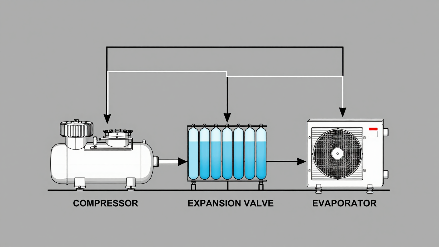
- Engineering Resolution: Only a refrigerant-based system like a miniature compressor can reliably and efficiently move heat against a thermal gradient to cool below ambient.
- Integration Trade-off: This requires integrating an evaporator (cold side) and condenser (hot side), which adds mechanical complexity. While Peltier coolers are an alternative for below-ambient cooling, they tend to be significantly less efficient, especially as the temperature difference between the hot and cold sides increases.
Gate 3: The High Heat Flux Constraint
- Constraint: The instrument generates a significant amount of heat from a small source (high heat flux), or the total thermal load is simply too high for air to remove from a compact enclosure.
- Decision Trigger: The system experiences a recurring IVD instrument thermal shutdown under peak load, confirming that the heat generation rate overwhelms the heat removal rate.
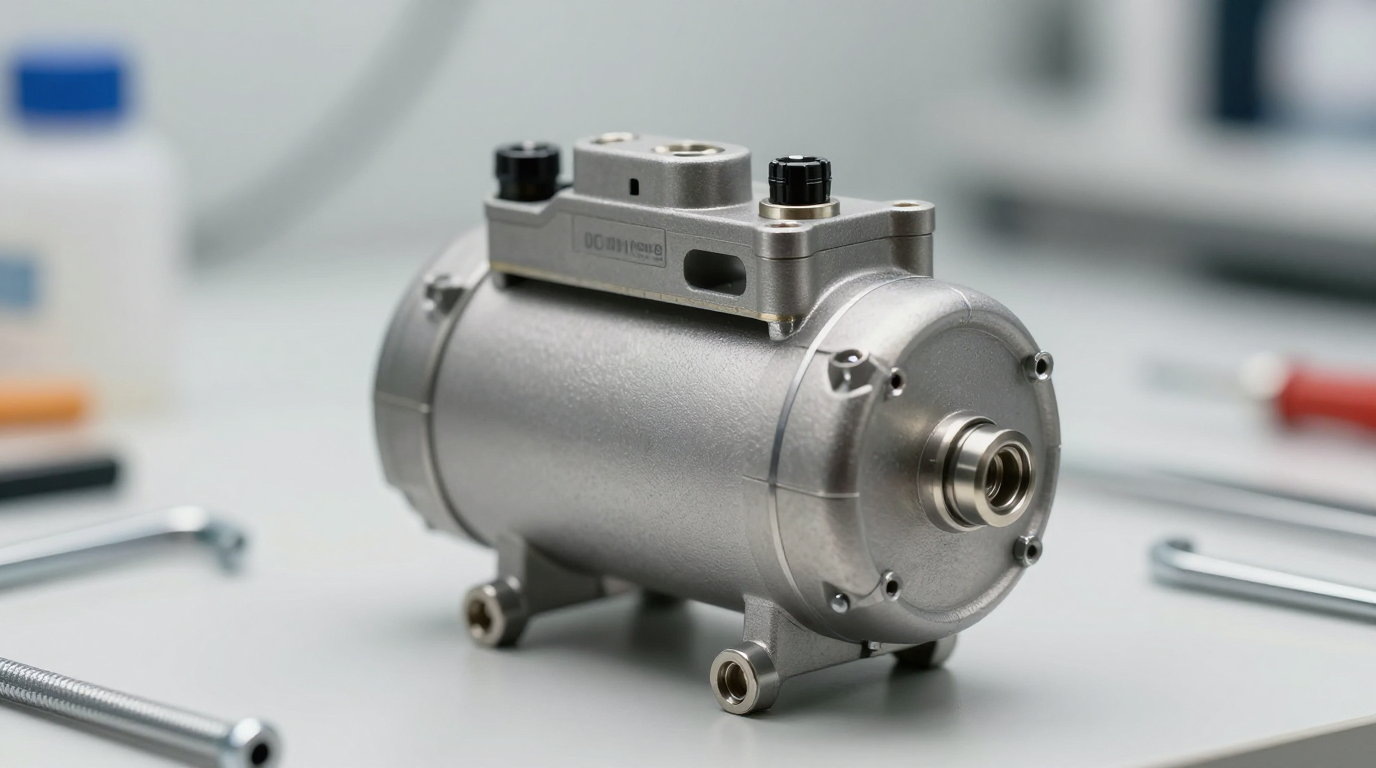
- Engineering Resolution: A miniature DC compressor system offers high cooling capacity in a very compact form factor. This high heat flux density capability is essential for managing powerful, small-footprint electronics.
- Integration Trade-off: The design must include a DC power supply capable of handling the compressor’s startup and operational current draw. The control system must also be integrated to manage compressor speed based on thermal feedback.
Integration Notes for Miniature Compressor Systems
Moving to a miniature compressor is not a drop-in replacement; it’s a system-level design choice. Success depends on thoughtful integration across several domains. This is not a step-by-step guide but a collection of field notes on key considerations.
- Mechanical: Vibration and noise are primary concerns. Use correctly specified rubber grommets and mounting brackets to isolate compressor micro-vibrations from the chassis. The evaporator needs a solid thermal connection to the component or liquid being cooled, while the condenser must be positioned for maximum airflow from a fan.
- Electrical: The DC power source must be clean, stable, and sized for both the inrush current at startup and the variable load from the compressor’s driver board. The driver board itself requires control signals (often PWM or a serial interface) from the instrument’s main controller to manage compressor speed based on real-time temperature data.
- Thermal: This is the most critical area. The heat removed from the cold side, plus the waste heat from the compressor motor itself, is all rejected at the condenser. Failing to properly ventilate the condenser will simply move the thermal problem from one part of the enclosure to another. Additionally, the cold side components (evaporator, suction line) must be well-insulated to prevent parasitic heat gain and to keep surfaces from falling below the dew point, which would cause condensation.
- Maintenance: Modern miniature compressor systems are hermetically sealed, closed-loop systems. They are designed to be maintenance-free and do not require refrigerant servicing over their operational life. The only maintenance task is ensuring that the condenser and its associated fan remain free of dust and debris that could impede airflow and reduce system efficiency.
Frequently Asked Questions
- Our enclosure is tightly packed. Isn’t a compressor system too large?
- Miniature DC compressor systems are specifically designed for applications with tight space constraints. Their compact, low-profile form factor often allows them to be integrated into spaces where other active cooling solutions might not fit.
- We’re concerned about power consumption. How efficient are these compressors?
- They are characterized by a high Coefficient of Performance (COP), meaning they move a significant amount of heat for the electrical energy they consume. Their variable-speed nature also means they only use the power necessary to meet the current thermal load, making them highly efficient during partial-load conditions.
- Can a miniature compressor handle the peak processing loads of our analyzer?
- Yes, these systems are engineered for high heat flux density. They excel at removing large amounts of heat from concentrated sources, making them well-suited for handling the peak thermal loads generated by modern processors and electronics during intensive analysis cycles.
- What about noise? Our instrument is used in quiet lab environments.
- These compressors are designed for low-noise operation. When combined with proper mounting and vibration isolation, their acoustic signature can be managed to be suitable for deployment in noise-sensitive medical and laboratory settings.
- Our current TEC cooler creates condensation. How does a compressor system prevent this?
- The system itself doesn’t inherently prevent condensation. Proper system design, including thorough insulation and sealing of all cold-side components, is critical to manage the dew point and prevent moisture formation. This is an integration responsibility.
- How difficult is it to control the compressor’s cooling output?
- Control is typically straightforward. The driver electronics accept common control inputs like PWM or serial commands, allowing for precise, variable-speed operation that can be easily integrated into the instrument’s overall thermal management algorithm.

Conclusion: Moving from Heat Mitigation to Thermal Management
Air cooling is effective for mitigating heat in systems with low-to-moderate, stable thermal loads. However, when an instrument’s core function and reliability are compromised by high heat density, dynamic loads, or the need for below-ambient cooling, a more robust solution is required. A recurring IVD instrument thermal shutdown is a clear signal that the physical limits of passive and fan-based cooling have been reached.
A miniature DC compressor is a strong engineering choice for systems requiring high-performance, stable, and compact cooling. It represents a shift from simply getting rid of waste heat to precisely managing the thermal environment. The decision hinges on whether the engineering challenge is one of simple heat removal or precise, reliable temperature control. For complex thermal challenges in compact medical or diagnostic devices, direct vapor compression cooling offers a level of performance and control that other systems often cannot match.
Explore the specifications for a miniature DC compressor to see if it aligns with your system’s demanding thermal requirements.


0 条评论