Field Snapshot: Afternoon Alarms and the Search for an IVD Analyzer Cooling Solution 24V
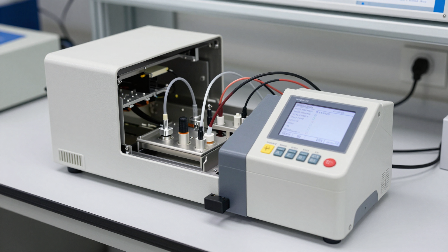
We were on-site with an OEM partner whose in-vitro diagnostic (IVD) analyzer was flagging temperature drift alarms. The pattern was consistent: the instrument performed within spec during morning calibrations, but once the sample chamber was fully loaded in the afternoon, thermal stability was lost. The core engineering constraints were immediately clear: the internal chassis was crowded, leaving minimal space for a cooling system, and the entire platform was powered by a 24V DC bus. The stakes are always high in diagnostics—sample integrity and test accuracy are non-negotiable.
This situation forces a critical design decision away from simple air-cooling or basic thermoelectric modules toward a more robust solution. By the end of this field note, you’ll be able to determine the decision gates that lead to specifying a miniature vapor-compression system for applications like this, where space, power, and thermal stability are in conflict.
First Checks: What We Looked at On-Site
Before considering a system redesign, we started with the fundamentals. In any diagnostic scenario involving thermal drift, these initial checks help isolate the root cause and prevent over-engineering a solution.
- Check: Mapped the ambient temperature profile of the lab from morning to late afternoon.
Why: A rising ambient temperature throughout the day can saturate a passive or undersized active cooling system, revealing that the issue isn’t a component failure but a design limitation.
What it suggests: The existing cooling hardware lacks the capacity to handle the combined internal heat load and the peak afternoon ambient heat load. - Check: Verified all airflow pathways, including intake vents, exhaust ports, and internal fans.
Why: Dust buildup or an inadvertently blocked vent is a common and simple failure point. It’s the first thing to rule out.
What it suggests: If airflow is clear but the temperature still climbs, the problem lies with the cooling technology’s ability to remove heat, not just move air. - Check: Measured the temperature directly at the sample chamber versus the general internal chassis temperature.
Why: This helps differentiate between a localized hotspot and a system-wide cooling deficit. The heat load from motors, processors, and the samples themselves can overwhelm a cooling system not designed for that specific thermal point.
What it suggests: A need for targeted, high-capacity spot cooling rather than simply increasing general chassis ventilation.
Common Failure Modes & Design Constraints
When initial checks don’t resolve the issue, we look for patterns that point to a fundamental mismatch between the thermal load and the cooling system. Here are the symptoms we often encounter in compact diagnostic instruments.
- Symptom: Temperature alarms trigger only under full sample load.
Likely Cause: The system’s total heat load (electronics + samples) exceeds the cooling capacity of the existing fan and heatsink.
Why it matters: Sizing a cooling system based on idle or average power draw is a common mistake; it must be designed for peak thermal load to ensure diagnostic accuracy. - Symptom: Existing fans are running at maximum speed, but the internal temperature continues to rise.
Likely Cause: The cooling system has reached thermal saturation. The temperature difference (ΔT) between the heatsink and the ambient air is too low for effective heat transfer.
Why it matters: This indicates that forced air cooling is no longer sufficient, and a technology that can actively pump heat is required. - Symptom: Wide temperature oscillations around the setpoint.
Likely Cause: A low-efficiency thermoelectric (Peltier) cooler using a simple on/off control loop.
Why it matters: Many reagents and biological samples require stable temperatures. Wide swings can compromise results, making a modulating system a better fit. - Symptom: Premature failure of electronic components near the sample chamber.
Likely Cause: Localized heat is not being effectively removed, accelerating component aging.
Why it matters: An effective IVD analyzer cooling solution 24V must protect the entire instrument, not just the samples. - Symptom: The instrument’s physical footprint is strictly defined, leaving no room for larger heatsinks or fans.
Likely Cause: The product design is mature, and mechanical changes are prohibitively expensive.
Why it matters: The cooling solution must offer high cooling density (high capacity in a small volume).
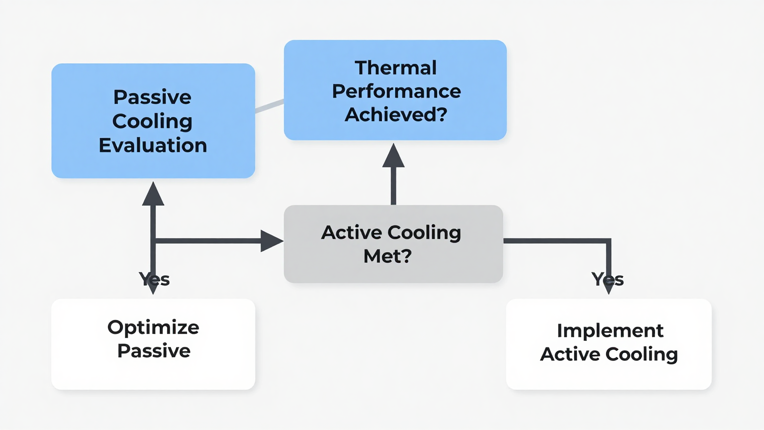
Decision Gates for Moving to Active Cooling
When faced with these constraints, a series of decision gates can clarify the path forward. If you answer yes to any of these, a miniature vapor-compression system becomes a primary candidate.
Gate 1: Is the Required Internal Temperature Below Ambient?
- Constraint: The sample chamber must be held at a temperature below the surrounding lab environment.
- Decision Trigger: Fans and heatsinks cannot, by definition, cool below ambient temperature. Thermoelectric coolers can, but often with significant efficiency penalties, especially as the temperature difference increases.
- Engineering Resolution: A vapor-compression cycle is a highly efficient method for creating a temperature differential and actively moving heat out of an enclosure.
- Integration Trade-off: This approach requires a closed-loop refrigeration circuit (evaporator, condenser, expansion valve, compressor), which is more complex than a simple fan but offers substantially higher performance.
Gate 2: Does the Peak Heat Load Exceed 100-150W in a Tight Space?
- Constraint: The combined heat from electronics and biological processes creates a peak load that overwhelms the current system.
- Decision Trigger: While large Peltier modules can handle higher heat loads, their low Coefficient of Performance (COP) means they generate significant waste heat of their own, further burdening the system.
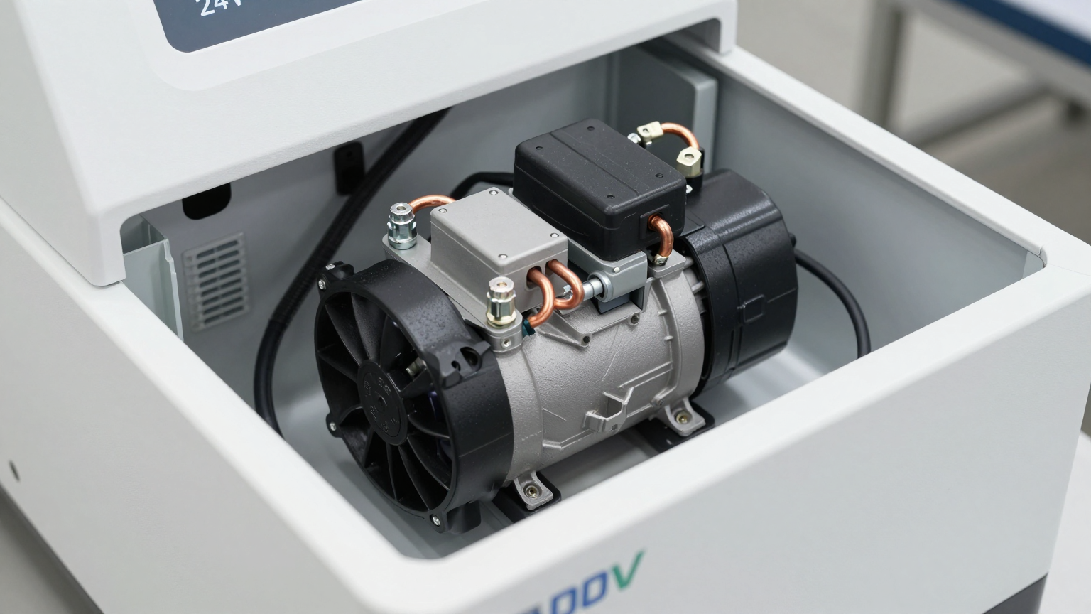
- Engineering Resolution: A miniature DC compressor can provide a high cooling capacity—up to 450W in some configurations—within a very small footprint (e.g., 76.8 x 55.8 x 48 mm).
- Integration Trade-off: The system must be designed to manage this capacity. A variable-speed driver is typically used to modulate the compressor’s output, matching cooling power to the real-time heat load and improving overall system stability.
Gate 3: Is Temperature Stability of +/- 0.5°C or Better Required?
- Constraint: Reagent and sample integrity demand precise, stable temperature control without significant overshoot or undershoot.
- Decision Trigger: Simple on/off control systems, common with thermoelectric coolers, often produce temperature swings that are unacceptable for sensitive applications.
- Engineering Resolution: A variable-speed miniature compressor allows for proportional control. By adjusting compressor speed, the system can precisely match the cooling rate to the heat load, achieving tight stability, often within +/- 0.5°C.
- Integration Trade-off: The control logic is more sophisticated than a simple thermostat, requiring a driver board that can interpret sensor feedback and manage compressor speed via a PWM or serial signal.
Integration Notes: Mechanical, Electrical, and Thermal
Specifying a miniature compressor is one part of the solution. Integrating it successfully requires a system-level approach. This is not a drop-in replacement for a fan.
- Mechanical: The compact size and low weight (around 480g) are key advantages. Mounting must account for managing the low vibration inherent in any compressor. Flexible refrigerant lines can help isolate the compressor from the chassis and sensitive components.
- Electrical: The system runs on 24V DC, making it directly compatible with the power architecture of many diagnostic instruments. A dedicated driver board is required to provide the correct power phase and control logic to the compressor motor.
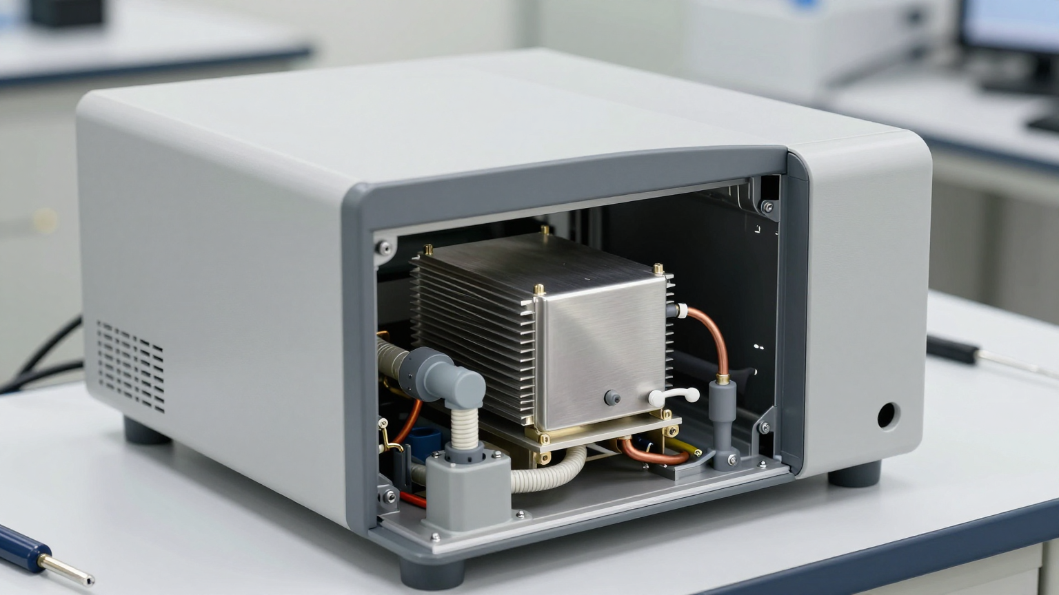
- Thermal: This is a closed-loop system. The evaporator (the cold side) must be placed to absorb heat from the target zone (e.g., a cold plate under the sample chamber). The condenser (the hot side) must be positioned to exhaust waste heat out of the instrument, typically with its own fan. Proper insulation between the cold and hot sides is critical for performance.
- Maintenance: Because it is a hermetically sealed system, a vapor-compression loop is generally a very low-maintenance solution over the life of the instrument, with no filters to clean or fans that are easily clogged.
Frequently Asked Questions
Our chassis is already full. Can a system like this really fit?
It depends on the specific layout, but the compressor itself is extremely compact, with dimensions around 76.8 x 55.8 x 48 mm. The challenge is typically in routing the refrigerant lines and placing the small evaporator and condenser, which offers more layout flexibility than a single, bulky thermoelectric assembly.
What is the power consumption like on a 24V bus?
Power draw is variable and depends on the heat load. The key advantage of a miniature vapor-compression IVD analyzer cooling solution 24V is its high efficiency (COP). It uses less power to move the same amount of heat compared to a Peltier device, which can free up power budget for other components.
We have sensitive optics and fluidics. Is vibration a concern?
The compressors are designed for low-vibration operation. However, for the most sensitive applications, proper mechanical isolation using grommets and flexible refrigerant lines is a standard part of the integration process to ensure no interference with other systems.
How is this better than the high-capacity Peltier cooler we are considering?
The primary advantages are efficiency and cooling density. A miniature compressor provides more cooling capacity (watts) per unit of volume and per watt of input power. This means a smaller, lighter solution that generates less waste heat for the same amount of cooling.
What kind of temperature stability can we realistically achieve?
With a properly tuned variable-speed controller and good thermal design, maintaining stability of +/- 0.5°C at the sensor location is a very achievable specification for this technology.
Does this require specialized refrigerant handling on our production line?
These systems are typically delivered as pre-charged, sealed loops consisting of the compressor, condenser, and evaporator. This can minimize the need for specialized refrigerant handling equipment during the final assembly of the instrument.
Conclusion: When to Make the Switch
For compact, 24V-powered instruments like IVD analyzers, relying on traditional fans or thermoelectric modules can lead to performance ceilings, especially as device complexity and heat loads increase. The decision to move to a miniature vapor-compression system is triggered when the application demands high-capacity cooling in a tight space, sub-ambient temperatures, or precise thermal stability that other technologies struggle to deliver efficiently.
If your project is hitting a thermal wall due to space, power, and stability constraints, exploring a miniature compressor-based approach is a logical next step. You can find more detailed specifications for these types of components on our miniature DC compressor product page.


0 条评论