Field Snapshot: Stabilizing EO/IR with a UAV Sensor Cooling Miniature Compressor
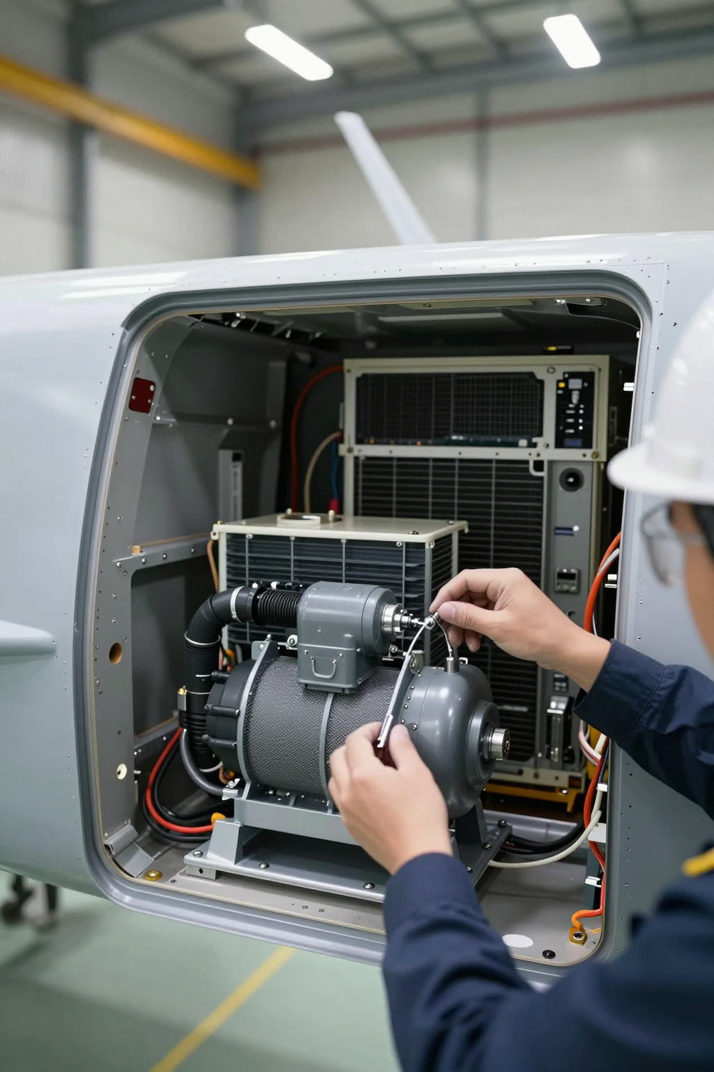
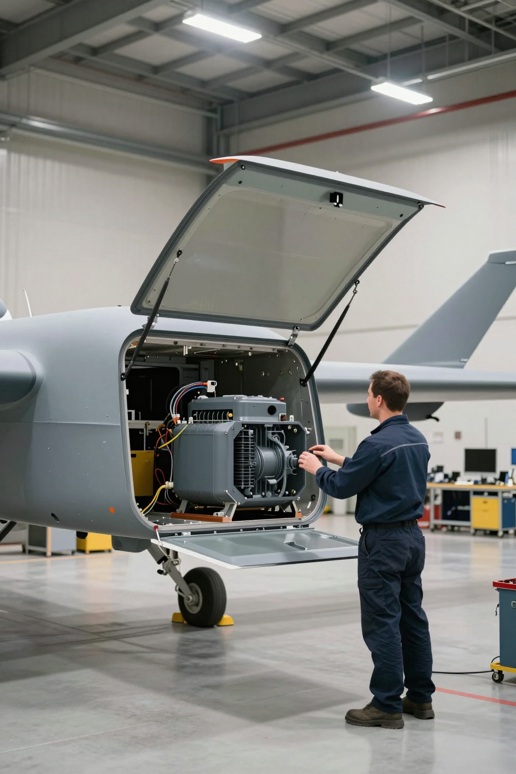
We were on a project involving a high-altitude, long-endurance (HALE) UAV. The primary payload, a high-sensitivity EO/IR sensor gimbal, was experiencing significant thermal drift during sustained operation above 20,000 feet. The initial passive cooling and TEC (thermoelectric cooler) setup couldn’t maintain the focal plane array’s required stable temperature, leading to noisy, unreliable data. The constraints were severe: a cramped payload bay, a strict power budget, and constant, high-frequency vibration from the aircraft. This field note walks through the decision process that leads an engineering team toward active refrigeration. By the end, you’ll be able to determine the key thresholds where a UAV sensor cooling miniature compressor becomes a primary candidate for your design.
First Checks: Initial Thermal Triage
Before considering a system overhaul, we always start with the fundamentals. In a situation like this, the initial triage focuses on quantifying the problem beyond “it’s running hot.”
- Check: Total heat load (Q_total) from the sensor electronics and environmental ingress.
Why: An underestimation of the total thermal load is a common failure point. Peak load during sensor processing often exceeds the average load that many passive or TEC systems are designed for.
What it suggests: If the peak load is significantly higher than the baseline, a dynamic cooling solution that can ramp up is likely necessary. - Check: Ambient temperature range at operational altitude vs. required sensor temperature.
Why: The temperature difference (Delta-T) is a critical driver of cooling system choice. High-altitude air is cold, but solar radiation and low air density reduce convective cooling efficiency, while internal electronics keep generating heat.
What it suggests: A large, persistent Delta-T often pushes beyond the practical efficiency limits of thermoelectric coolers. - Check: Available DC power budget and voltage stability.
Why: All active cooling systems require power. The question is how much, at what voltage, and how clean the power needs to be. A miniature vapor-compression system has a different power profile than a TEC.
What it suggests: If the power budget is tight but the cooling demand is high, efficiency (Coefficient of Performance, or COP) becomes the most important metric, favoring systems like a miniature compressor.
Common Failure Modes and Constraints
When initial solutions fail in the field, the symptoms point toward underlying physical constraints. Here are the typical failure modes we encounter when dealing with high-performance sensor cooling.
- Symptom: Image noise increases over the duration of the flight.
Likely Cause: The TEC is saturated. It cannot pump heat away fast enough, causing the sensor’s temperature to slowly drift upwards. TECs become notably less efficient as the Delta-T increases.
Why it matters: Unstable sensor temperature makes data calibration difficult, if not impossible, compromising mission objectives. - Symptom: Cooling performance drops significantly during aircraft maneuvers.
Likely Cause: The passive heat sink’s effectiveness is tied to consistent airflow, which can be disrupted during banking or altitude changes.
Why it matters: A reliable cooling system must be largely independent of platform orientation or flight dynamics. - Symptom: The existing TEC solution draws excessive current, threatening the power budget for other avionics.
Likely Cause: The TEC is operating at its maximum voltage to cope with the heat load, a range where its COP is very low.
Why it matters: Robbing power from other systems can lead to cascading failures. An efficient cooling solution uses less power for the same amount of heat removal. - Symptom: Intermittent system resets or shutdowns.
Likely Cause: High inrush current from the cooling system is causing voltage droop on the DC power bus.
Why it matters: Power stability is critical for sensitive electronics. The cooling system’s electrical footprint must be compatible with the host platform. - Symptom: Premature failure of the cooling fan or TEC module.
Likely Cause: High-vibration environment exceeding the design limits of commercial off-the-shelf components.
Why it matters: In UAV applications, reliability and maintenance intervals are paramount. Components must be specified for the shock and vibration profile of the aircraft.
Decision Gates for Active Refrigeration
Moving to a miniature vapor-compression cycle is a significant design choice. The decision is typically forced by crossing one or more of these engineering thresholds.
Gate 1: Heat Load and Density
- Constraint: The total heat load from the sensor package exceeds 100-150W in a compact space.
- Decision Trigger: At this heat density, passive solutions become too large and heavy. TECs become inefficient, generating more waste heat of their own and drawing excessive power.
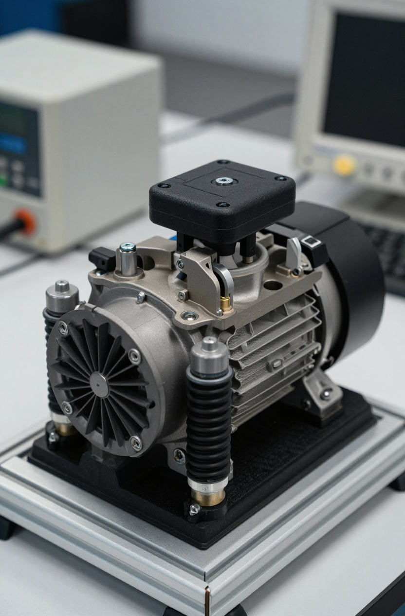
- Engineering Resolution: A miniature rotary compressor system. A system like the Arctic-tek 12V mini-compressor can provide up to 450W of cooling capacity, offering enough headroom for peak loads and future sensor upgrades.
- Integration Trade-off: This approach introduces refrigerant and requires a closed loop with an evaporator and condenser, adding mechanical complexity compared to a solid-state TEC.
Gate 2: Weight and Volumetric Constraints
- Constraint: The entire cooling solution must fit within a payload enclosure with minimal volume, and every gram counts.
- Decision Trigger: The required heatsinks for passive or TEC systems would make the payload too large or heavy.
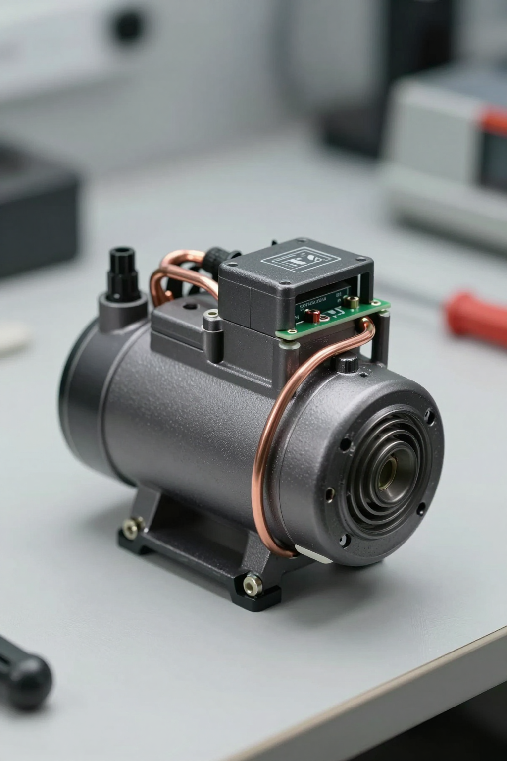
- Engineering Resolution: A highly compact compressor. The core component can be exceptionally small, with a typical weight of around 560 grams and dimensions of roughly 56 mm in diameter and 79 mm in height. This allows for flexible placement of the condenser and evaporator.
- Integration Trade-off: While the compressor itself is small, the system requires careful layout and plumbing of refrigerant lines for the condenser and evaporator, which must be integrated into the payload structure.
Gate 3: Power Efficiency (COP)
- Constraint: The aircraft’s DC power bus has limited surplus capacity, making cooling efficiency a primary design driver.
- Decision Trigger: The COP of the existing TEC solution is below 1.0, meaning it generates more heat than it moves.
- Engineering Resolution: A variable-speed UAV sensor cooling miniature compressor. Vapor-compression cycles are inherently more efficient, and the ability to adjust compressor speed to match the real-time thermal load prevents wasted energy.
- Integration Trade-off: Requires a sophisticated motor controller (driver board) that can manage the variable-speed operation and respond to temperature feedback. The power supply must be a stable 12V DC source.
Integration Notes: Field Observations
Integrating a miniature compressor is not a drop-in replacement. It’s a system design shift. Here are some notes from the field.
- Mechanical: The compressor’s rotary design is inherently balanced, producing low vibration. However, proper mounting with vibration-damping grommets is still recommended to isolate it from the sensor. The unit can typically be mounted in any orientation, which provides significant flexibility for packaging.
- Electrical: A stable, low-ripple 12V DC power source is critical. The driver board controls the compressor speed via a PWM or analog signal. It’s important to account for the initial inrush current during startup, although it is managed by the controller.
- Thermal: Condenser performance is key. It needs dedicated airflow, which can be managed with a small, high-static-pressure fan. The evaporator must be designed for maximum thermal contact with the component being cooled—often a custom cold plate integrated into the sensor housing.
- Maintenance: These are hermetically sealed systems, designed to be maintenance-free for the life of the unit. The primary reliability factors are the fan for the condenser and the cleanliness of the condenser fins.
Frequently Asked Questions (FAQ)
How does high altitude affect the compressor system?
The lower air density at altitude reduces the effectiveness of the air-cooled condenser. It’s often necessary to use a slightly larger condenser or a higher-speed fan than would be required at sea level to achieve the same heat rejection.
Is a miniature compressor too heavy for a small UAV?
While heavier than a small TEC module alone, a full system comparison is more accurate. When you add the large heatsink and fan required for a high-power TEC, the total weight of a UAV sensor cooling miniature compressor system can be competitive, especially given its superior cooling capacity.
What is the power draw compared to a TEC?
For a given cooling load, the compressor system will almost always draw less power due to its higher COP. The power draw is variable, scaling with the heat load, which saves energy during periods of low sensor activity.
Can this system handle the vibration of a UAV launch and flight?
These compressors are designed for mobile applications and are built to withstand significant shock and vibration. The key is proper mechanical integration and mounting to avoid transmitting vibration to sensitive components.
How do you control the temperature precisely?
A closed-loop control system is used. A temperature sensor on the EO/IR device provides feedback to the compressor’s driver board, which adjusts the compressor speed to maintain a stable setpoint temperature.
What kind of cooling capacity can I expect?
Depending on the operating conditions (evaporating and condensing temperatures), a miniature compressor of this class can deliver from 100W up to 450W of cooling.
Conclusion: When to Make the Switch
For low-power sensors with minimal thermal challenges, passive and TEC solutions remain viable. However, for high-performance EO/IR systems deployed on high-altitude platforms, the physics of heat density, power efficiency, and thermal stability often push the design toward active refrigeration.
If your project is hitting the thermal limits of solid-state cooling, experiencing data degradation from temperature drift, and has a strict weight and power budget, a UAV sensor cooling miniature compressor is a compelling engineering path. It resolves the core issues of high heat flux and poor TEC efficiency that are common in demanding aerospace applications.
To review the specifications of a compressor designed for these environments, see our technical data on the Arctic-tek 12V Miniature DC Compressor.


0 条评论