Why Your Control Cabinet Trips in Summer: A Guide to the Micro DC Air Conditioner Control Cabinet
An operator reports a drive fault. The maintenance team investigates and finds a VFD that has tripped on an over-temperature alarm. They check the drive parameters, verify the load, and find no immediate electrical cause. After a reset, the system runs, only to trip again hours later when the afternoon sun hits the plant wall. This isn’t an electrical problem; it’s a thermal one masquerading as a fault. These nuisance trips erode production time and lead to costly, unnecessary component replacements. The real issue is that the control cabinet’s thermal management system—if one even exists beyond a simple vent—has failed to keep pace with the internal heat load and the rising ambient temperature.
Failing to address this core problem leads to a cascade of failures, from degraded power supply performance to premature aging of PLCs and contactors. By the end of this article, you will be able to diagnose the thermal failure modes in your own enclosures and determine the precise threshold where passive cooling fails and an active solution, like a micro dc air conditioner control cabinet, becomes a necessity. We will prioritize closed-loop, sealed-enclosure cooling over simple ventilation because in industrial environments, protecting electronics from contaminants is as critical as protecting them from heat.
Deployment Context: Two Common Overheating Scenarios
The transition from a stable system to one plagued by thermal faults is often subtle, triggered by a change in environment or equipment. Here are two typical scenarios where control cabinet overheating becomes a critical issue.
Scenario A: The Upgraded Production Line
A packaging facility upgrades a conveyor line, replacing an old AC motor with a new servo system controlled by a VFD. The new drive is installed in the existing, sealed NEMA 4 cabinet. For the first few months in winter, everything runs flawlessly. But as summer arrives and ambient temperatures in the non-air-conditioned facility climb past 35°C (95°F), the VFD begins to trip intermittently during high-throughput runs. The root cause isn’t the drive itself; it’s the increased thermal load inside a sealed box that was never designed for that level of heat dissipation. The constraint is the sealed enclosure, which prevents the use of simple fans without compromising its rating against washdowns and dust.
Scenario B: The Outdoor Telecom & Edge Compute Shelter
A remote telecom shelter houses power distribution units, backup batteries, and networking hardware in a NEMA 3R enclosure. The original design relied on passive ventilation and the sheer thermal mass of the cabinet. However, a recent 5G equipment upgrade added significant processing load and, consequently, more heat. Now, on sunny days, direct solar radiation combined with the new internal load pushes internal temperatures well above the 60°C (140°F) operating limit of the sensitive electronics. The system experiences data packet loss and modem resets, which were initially misdiagnosed as a software issue. The dominant constraint here is the extreme ambient condition, including solar load, which makes any form of passive cooling completely ineffective.
Common Failure Modes & Constraints
Overheating doesn’t just cause a single, dramatic failure. It creates a series of compounding problems that can be difficult to diagnose. Here are the most common failure modes, ranked by their likelihood and operational impact.
- Symptom: VFD or servo drive nuisance trips → Cause: Drive’s internal heatsink temperature exceeds its software limit, triggering a protective shutdown → Why it matters: Causes unplanned downtime and lost production cycles.
- Symptom: “Ghost” faults or PLC logic errors → Cause: Semiconductor components operate unreliably above their rated temperature, causing unpredictable behavior → Why it matters: Erodes trust in the control system and leads to time-consuming troubleshooting.
- Symptom: Premature power supply failure → Cause: Electrolytic capacitors degrade exponentially faster at higher temperatures, leading to reduced lifespan and voltage instability → Why it matters: A failing PSU can bring down the entire control system.
- Symptom: Darkened or distorted HMI screens → Cause: LCD screens are highly sensitive to heat, which can cause permanent damage to the display crystals → Why it matters: Loss of operator interface can be a safety and operational hazard.
- Symptom: Breakers tripping below their rated current → Cause: Thermal-magnetic breakers are de-rated at high ambient temperatures, causing them to trip sooner → Why it matters: Leads to misdiagnosis of overcurrent faults.
- Symptom: Dust and grime coating internal components → Cause: Using unfiltered fans pulls in airborne contaminants, which insulate components and cause them to run even hotter → Why it matters: Violates the enclosure’s IP/NEMA rating and creates a new failure vector.
- Symptom: Evidence of condensation or corrosion → Cause: Bringing hot, humid ambient air into a cooler cabinet with a fan can cause moisture to condense directly onto electronics → Why it matters: Creates a risk of short circuits and long-term corrosion damage.

Engineering Fundamentals: Closed-Loop Cooling vs. Ventilation
To select the right thermal solution, it’s crucial to understand the fundamental difference between simply moving air and actively removing heat. The goal inside a control cabinet is to move heat from the sensitive components (like a VFD’s heatsink) to the outside of the sealed enclosure.
A simple fan and filter assembly works on the principle of ventilation. It creates an open loop, pulling in cooler ambient air from the outside, circulating it through the cabinet, and exhausting the heated air. This only works if two conditions are met: the ambient air is significantly cooler than the desired internal temperature, and the ambient air is clean and dry. In most industrial settings, neither is a guarantee. This open-loop approach is a direct violation of any NEMA 12, 4, or 4X rating, as it exposes the internal electronics to dust, moisture, and corrosive agents.
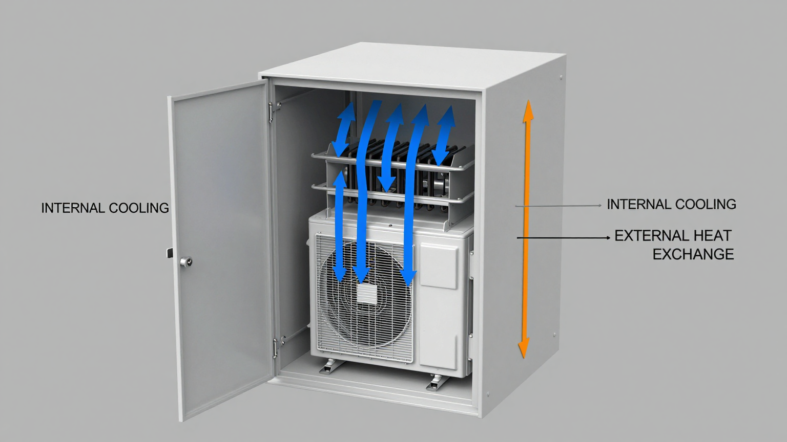
A micro dc air conditioner control cabinet, by contrast, creates two separate, closed air loops.
- The Internal Loop: A blower inside the unit pulls hot air from the top of the cabinet, passes it over a cold evaporator coil where heat is absorbed, and returns chilled, dehumidified air to the bottom of the cabinet. The internal air never mixes with the outside environment.
- The External Loop: A second fan pulls ambient air from the outside, passes it over a hot condenser coil to discharge the captured heat, and exhausts it back to the environment.
Common Misconception: “More airflow (higher CFM) from a fan is always better.”
Correction: This is only true if the outside air is cool enough to absorb the heat. If the internal heat load is 500 watts and the ambient temperature is already 40°C, no amount of 40°C air from a fan can cool the components to a safe operating temperature of 35°C. This is a fundamental limitation of thermodynamics. Active cooling with a vapor-compression system, like a micro dc aircon for VFD cabinet, is required to create a temperature differential and actively pump heat out of the enclosure, even when the outside air is hot. This is the only way to maintain a stable internal temperature regardless of external conditions.
Key Specifications for a Micro DC Air Conditioner Control Cabinet
When evaluating a DC enclosure air conditioner, certain specifications are non-negotiable go/no-go gates for your project. These figures determine if the unit can handle the thermal load, fit the physical constraints, and integrate with your power system. Below are key parameters for the Rigid Chill Micro DC Aircon series, which are designed for these compact industrial applications.
| Model (Example) | Input Voltage | Nominal Cooling Capacity | Refrigerant |
|---|---|---|---|
| DV1910E-AC (Pro) | 12V DC | 450W | R134a |
| DV1920E-AC (Pro) | 24V DC | 450W | R134a |
| DV1930E-AC (Pro) | 48V DC | 450W | R134a |
| DV3220E-AC (Pro) | 24V DC | 550W | R134a |
How to read these specs for your decision:
- Input Voltage: This is the first gate. The unit’s voltage must match your control panel’s DC bus (typically 12V, 24V, or 48V). Using native DC power avoids the inefficiency and extra heat of an AC-to-DC power conversion.
- Nominal Cooling Capacity (Watts): This must be greater than the total heat load generated by all components inside the cabinet (VFDs, power supplies, PLCs, etc.). Always engineer with a safety margin of 20-25%.
- Physical Dimensions & Mounting: The unit’s height, width, and depth determine if it can be mounted on the cabinet door or side wall without interference. This is a critical go/no-go check. (Note: Dimensions vary by model).
- Operating Temperature Range: Ensure the unit is rated to operate in your maximum expected ambient temperature. A standard unit may struggle in a desert or steel mill environment.
For more details on compact cooling solutions, see our overview of Micro DC Aircon products.
Engineering Selection Matrix: Logic Gates for Integration
Choosing the right thermal management solution involves a series of logical decisions. An engineer must evaluate the constraints and select a path that guarantees reliability. Here are three critical logic gates you must pass through.
Logic Gate 1: Thermal Delta vs. Ambient Ceiling
- The Constraint Gate: The difference between the maximum allowable internal cabinet temperature and the peak ambient external temperature.
- The Decision Trigger: If the peak ambient temperature is ever expected to be equal to or higher than the required internal temperature, passive cooling (fans, vents, heat exchangers) is physically incapable of working. For example, if your VFDs must be kept below 40°C, but the factory floor hits 45°C in the summer, you cannot use a fan.
- Engineering Resolution: This condition mandates the use of an active, refrigerant-based system. A micro dc air conditioner control cabinet is the direct solution, as it can create a “sub-ambient” internal temperature, actively pumping heat out against the thermal gradient.
- Integration Trade-off: This requires allocating a dedicated power budget from the DC bus for the compressor and fans. However, it guarantees that the electronics will operate within their specified temperature range, eliminating thermal derating and nuisance trips.
Logic Gate 2: Environmental Sealing vs. Contamination Risk
- The Constraint Gate: The required NEMA or IP rating of the enclosure to protect against environmental hazards like dust, moisture, or corrosive chemicals.
- The Decision Trigger: If the cabinet is located in an environment with airborne dust (e.g., woodworking, textiles), moisture (e.g., food processing washdowns), or salt fog (e.g., coastal installations), any solution that requires cutting an open vent (like a fan and filter) is a non-starter.
- Engineering Resolution: The only viable solution is a closed-loop cooling system that maintains the seal of the enclosure. A gasketed dc enclosure air conditioner for control panel mounts to the outside of the cabinet, ensuring the internal and external air paths remain completely separate and preserving the NEMA rating.
- Integration Trade-off: The initial cost is higher than a simple fan kit. However, this is offset by preventing the far greater cost of replacing an entire cabinet’s worth of electronics damaged by contamination. It’s an investment in system-level reliability.
Logic Gate 3: Power Density vs. Volumetric Footprint
- The Constraint Gate: The physical space available on or inside the control cabinet and the type of power available. Modern control panels are increasingly dense with components.
- The Decision Trigger: If the cabinet is small, wall-mounted, or part of a mobile system (AGV, robotics), a large, traditional AC-powered air conditioner is not feasible due to its size, weight, and power requirements.
- Engineering Resolution: Select a cooling solution with high power density that runs on native DC voltage. A micro dc air conditioner control cabinet leverages a miniature DC compressor and compact heat exchangers to provide significant cooling capacity in a small, lightweight package, avoiding the need for a separate AC circuit and bulky inverters.
- Integration Trade-off: Careful planning is needed for the mounting location to ensure proper airflow for both the internal and external loops. This may involve coordinating with the mechanical design team to reserve space on a door or side panel early in the design process.
Implementation Checklist: Installation and Verification
Proper installation is critical to the performance and longevity of any cabinet cooling solution. Follow this checklist to ensure a successful deployment.
-
Mechanical Installation
- Verify Mounting Surface: Ensure the cabinet door or wall is flat and strong enough to support the unit. Add stiffeners if necessary.
- Use the Gasket: The supplied gasket is not optional. It is essential for creating a perfect seal between the air conditioner and the cabinet to maintain the NEMA rating and prevent air leaks.
- Check Airflow Paths: Confirm that once mounted, the unit’s internal and external fans are not obstructed by other equipment, walls, or adjacent cabinets. A minimum clearance (typically 10-15 cm) is required.
-
Electrical Connection
- Confirm Power Budget: Verify that the 24V or 48V DC power supply has enough spare capacity to handle the air conditioner’s startup and running current.
- Use Correct Wire Gauge: Size the power wiring appropriately for the current draw and distance to prevent voltage drop.
- Install Overcurrent Protection: Connect the unit through a dedicated, correctly-sized fuse or circuit breaker as specified in the installation manual.
-
Thermal Verification
- Seal All Openings: Before commissioning, ensure all other holes, vents, and cable glands in the cabinet are properly sealed. The system must be a closed loop.
- Place a Temperature Sensor: For validation, place an independent thermocouple or data logger near the top of the cabinet, where the hottest air will accumulate.
- Perform a Load Test: Run the machinery under its highest normal load. Let the micro dc air conditioner control cabinet run and verify that the internal temperature stabilizes at or below your target setpoint.
-
Maintenance Planning
- Schedule Filter/Coil Cleaning: The external condenser coil will accumulate dust over time. Schedule periodic inspections and cleaning (using compressed air) to maintain heat transfer efficiency.
- Check for Condensate: Ensure the condensate drain line (if applicable) is clear and properly routed away from any sensitive equipment.
Frequently Asked Questions (FAQ)
1. Can’t I just use a bigger fan or a vortex cooler to solve VFD cabinet overheating trips?
A bigger fan still uses ambient air, so it won’t work if the outside air is too hot. A vortex cooler can provide sub-ambient cooling but is extremely inefficient, consumes a massive amount of compressed air (which is expensive to generate), and is very loud. A micro dc air conditioner control cabinet is far more energy-efficient and doesn’t require a compressed air supply.
2. What about condensation? Will an air conditioner create water inside my panel?
A properly designed cabinet air conditioner manages condensation. As it cools the internal air, moisture condenses on the cold evaporator coil. This water is collected in a tray and is typically evaporated into the external exhaust airstream. This process actively dehumidifies the cabinet, protecting components.
3. How do I handle a control cabinet that is in direct sunlight?
Direct solar radiation adds a significant heat load. You must calculate this solar load (a good rule of thumb is ~100 Watts per square foot of exposed surface) and add it to your internal heat load calculation. You will need a higher capacity cooling unit to compensate for both the internal and external heat sources.
4. My cabinet is in a dusty/dirty environment. How does that affect the choice?
In a dusty environment, a closed-loop solution is mandatory. Any open-loop fan will quickly clog with dust, and the abrasive or conductive dust will coat your electronics, causing failures. A dc enclosure air conditioner for control panel keeps the internal air clean while managing the heat.
5. What is the first thing I need to measure before selecting a cooling unit?
You need to calculate the total internal heat load in Watts. You can find the heat dissipation values in the datasheets for your VFDs, power supplies, PLCs, and other components. Sum them all up, then add a 20-25% safety margin.
6. How can I validate that the cooling solution is working correctly after installation?
The best method is to use a temperature data logger inside the sealed cabinet. Place it near the most heat-sensitive components or at the top of the enclosure. Record the temperature over a full production cycle on a hot day to confirm it remains stable and within the safe operating limits of your equipment.
7. Is a micro dc aircon better than a thermoelectric (Peltier) cooler?
For cooling capacities above 100-150 Watts, a vapor-compression micro dc air conditioner control cabinet is significantly more efficient (has a higher Coefficient of Performance) than a thermoelectric cooler. While thermoelectric units have no moving parts, they require much more electrical power to remove the same amount of heat, adding to your long-term operating costs.
Conclusion: The Right Tool for a Critical Job
Intermittent, heat-related faults are some of the most frustrating and costly issues in industrial automation. Misdiagnosing them as electrical problems leads to wasted time and unnecessary component replacement. The engineering-led approach is to treat the enclosure’s thermal stability as a critical system requirement, just like power quality or network integrity.
A fan-based solution is only appropriate for clean, cool environments where the enclosure does not need to be sealed. For the vast majority of industrial applications facing high ambient temperatures, humidity, dust, or the need to maintain a NEMA rating, a closed-loop active cooling system is the only reliable choice. A micro dc air conditioner control cabinet provides a robust, efficient, and compact solution specifically designed for these challenging scenarios. It ensures that your critical and expensive control components operate within their specified limits, maximizing uptime and extending their service life.
If you are facing challenges with control cabinet overheating and need to size a solution for your specific heat load, enclosure geometry, and power constraints, contact our engineering team to discuss a best-fit thermal management strategy.


0 条评论