Angle Lock: This article addresses the decision moment when selecting and integrating a compact vapor-compression cooling system into a sealed enclosure. We focus on two primary failure modes: gradual performance degradation from hidden airflow restrictions and catastrophic failure from under-sizing against peak thermal load. The dominant constraint is maintaining a closed-loop, sealed system integrity in mobile or harsh environments.
Why Your Micro DC Air Conditioner is Not Cooling: A System-Level Checklist
It’s a frustrating scenario for any system integrator or field engineer: the diagnostics show power, the compressor is running, fans are spinning, but the internal temperature of your electronics enclosure continues to climb. The system is technically “working,” but it isn’t cooling. This situation often points not to a faulty component, but to a fundamental mismatch between the cooling unit’s capabilities and the system’s real-world operational demands. The stakes are high—uncontrolled thermal runaway leads to processing errors, premature component failure, and costly downtime for critical mobile robotics, telecom equipment, or medical devices.
This guide provides a structured approach to compact system cooling troubleshooting. By the end, you will be able to diagnose the root cause of poor thermal performance and make informed decisions about system design, integration, and validation. We will move beyond simple component specs to analyze the complete thermal circuit, from heat source to ambient air. In this article, we prioritize system-level integration and heat load verification over component-level diagnostics, because this is where over 90% of performance issues originate in compact, sealed enclosures.
Deployment Context: Where Performance Fails Reality
Understanding the application environment is the first step in any effective troubleshooting process. Here are two common scenarios where a seemingly functional DC aircon fails to deliver the required cooling.
Scenario A: Mobile Robotics in a Dusty Warehouse
An autonomous guided vehicle (AGV) operates on a factory floor, navigating tight spaces and interacting with machinery. Its sealed control cabinet, housing the guidance computer and motor drivers, is protected by a Micro DC Aircon unit. After three months of service, the AGV begins experiencing intermittent processing faults on hot afternoons. Technicians confirm the DC aircon is running, but the cabinet’s internal temperature exceeds its 45°C threshold. The root cause wasn’t a component failure, but rather the gradual clogging of the condenser (hot side) fins with airborne dust and debris, severely restricting its ability to reject heat to the ambient environment. The constraint here was environmental contamination, which wasn’t accounted for in the maintenance schedule.
Scenario B: Outdoor Telecom Cabinet with Solar Load
A remote 4G/5G telecom repeater is housed in a NEMA-4 rated cabinet in a desert location. The system was sized based on the electronics’ waste heat, but engineers overlooked the intense solar radiation on the cabinet’s dark-colored surface. During peak daylight hours, the total heat load (electronics + solar gain) far exceeded the cooling capacity of the installed unit. The DC aircon running but no cooling was a direct result of an undersized unit facing an uncalculated peak thermal load. The dominant constraint was the external environmental heat load, which effectively consumed all the available cooling capacity before it could address the heat from the internal electronics.
Common Failure Modes & System Constraints
When a micro dc air conditioner is not cooling despite being powered on, the issue is almost always systemic. Here are the most common culprits, ranked by likelihood and impact. This is the core of your compact system cooling troubleshooting checklist.
- Symptom: High internal temperatures despite constant operation → Cause: Undersized cooling unit for the total heat load (internal electronics + solar/external gain) → Why it matters: The unit can never catch up, leading to chronic overheating and component derating.
- Symptom: Cooling performance degrades over time → Cause: Clogged condenser or evaporator air paths (dust, debris, oil) → Why it matters: Reduced heat exchange efficiency slowly suffocates the system, turning a functional unit into an ineffective one.
- Symptom: Unit cycles on and off frequently but never cools → Cause: Poor sensor placement giving false temperature readings → Why it matters: The controller thinks the job is done, shutting down prematurely while hotspots persist elsewhere in the enclosure.
- Symptom: Cold air is produced, but the cabinet remains hot → Cause: Air bypass or short-circuiting within the enclosure → Why it matters: The cooled air is immediately drawn back into the evaporator intake instead of circulating and absorbing heat from the electronics.
- Symptom: Visible condensation or water pooling → Cause: Air leaks in a sealed enclosure (compromised gasket) allowing humid ambient air to enter → Why it matters: The unit wastes energy dehumidifying incoming air instead of cooling the internal air, and condensation creates a risk of electrical shorts.
- Symptom: Unit performance drops significantly at high ambient temperatures → Cause: Insufficient condenser airflow or high backpressure → Why it matters: The unit cannot reject heat effectively, causing compressor head pressure to rise and cooling capacity to plummet.
- Symptom: Voltage drop at the unit under load → Cause: Inadequate wire gauge or a shared power supply with fluctuating loads → Why it matters: Low voltage reduces compressor and fan speed, directly cutting cooling capacity and potentially damaging the unit.
Engineering Fundamentals: The Closed-Loop Thermal Path
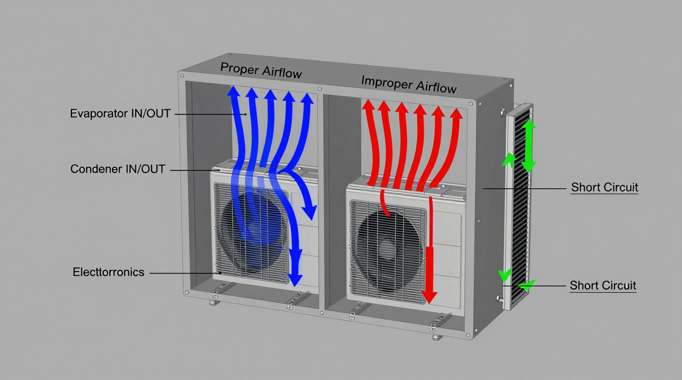
A micro DC air conditioner is a vapor-compression system designed for a closed-loop environment. This is the single most important concept to grasp. Unlike comfort cooling for rooms, its job is to move heat from the air inside a sealed cabinet to the air outside, without mixing the two. This process relies on two distinct airflow paths: the internal (evaporator) side and the external (condenser) side.
The internal loop pulls hot air from the top of the enclosure, passes it over the cold evaporator coil where heat is absorbed, and exhausts chilled air near the bottom to create a convection cycle. The external loop pulls ambient air from the surroundings, passes it over the hot condenser coil to expel the absorbed heat, and exhausts it away from the unit. Any breakdown in the integrity of these two paths is a primary reason for a micro dc air conditioner not cooling.
Misconception: A higher BTU or Watt rating is always better.
Correction: The right-sized unit is always better. An oversized unit will cool the air volume too quickly and cycle off, a phenomenon known as short-cycling. This prevents proper air circulation and dehumidification, leaving hotspots and potential condensation issues. More importantly, the high-capacity unit may draw more power than the system’s DC bus can reliably provide, creating electrical instability. The goal is not brute force, but balanced and continuous heat removal that matches the enclosure’s specific heat load.
Key Specifications for Troubleshooting and Selection
When diagnosing a cooling issue or selecting a new unit, you must look beyond the nominal cooling capacity. These specifications provide the context needed to understand a unit’s performance envelope. When a DC aircon is running but no cooling is occurring, the answer is often found by comparing the application’s demands against these datasheet limits.
| Model Series | Voltage | Nominal Cooling Capacity | Refrigerant | Key Feature |
|---|---|---|---|---|
| Micro DC Aircon (Pro) | 12V / 24V / 48V | 100W–900W | R134a | Integrated variable-speed inverter control |
| DV1920E-AC (Example) | 24V | 450W | R134a | Compact footprint for mobile applications |
| DV3220E-AC (Example) | 24V | 550W | R134a | Higher capacity for denser electronics |
How to read these specs for our decision: The Voltage must match your system’s power bus (e.g., 24V for industrial robotics). The Nominal Cooling Capacity is your starting point, but this number is rated at a specific indoor and outdoor temperature; it will be lower in more extreme conditions (derating). The Refrigerant type is important for service and compliance, but less so for initial troubleshooting. The key is to use this data as a baseline for the deeper analysis that follows.
Engineering Selection Matrix: Logic Gates for Integration
To prevent a cooling performance failure, every system design must pass through a series of logic gates. This matrix formalizes the decision-making process beyond just picking a part number. It’s a critical step in any robust compact system cooling troubleshooting effort.
Logic Gate 1: Total Heat Load vs. Nominal Capacity
- Constraint Gate: The total heat load that must be removed from the enclosure. This is not just the sum of the TDP of the electronics. It must also include heat gain from solar load, adjacent machinery, and any inefficiencies in the power system.
- Decision Trigger: If the calculated total heat load (Internal Watts + External Watts) exceeds 70-80% of the Micro DC Aircon’s nominal cooling capacity at the expected operating temperatures.
- Engineering Resolution: Select a unit with a higher capacity or, preferably, implement measures to reduce the heat load first (e.g., solar shielding, better insulation, relocating high-heat components). Relying on a cooling unit to operate at 100% duty cycle continuously is a recipe for premature failure.
- Integration Trade-off: A larger unit may have a bigger footprint and higher power draw. Reducing the heat load may require mechanical redesigns but results in a more reliable, efficient system.
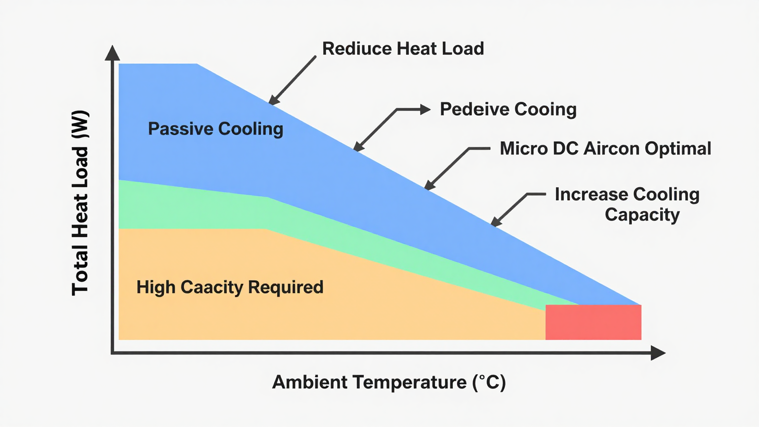
Logic Gate 2: Thermal Delta vs. Ambient Ceiling
- Constraint Gate: The difference between the maximum allowable internal enclosure temperature and the peak ambient external temperature.
- Decision Trigger: If the peak ambient temperature is close to or exceeds the maximum desired internal temperature. A simple fan or heat exchanger cannot work here, as they rely on a favorable temperature gradient.
- Engineering Resolution: This is the primary trigger for choosing an active, refrigerant-based system like a Micro DC Aircon. It is the only technology that can create a temperature differential against the ambient gradient, keeping internal components cooler than the outside air.
- Integration Trade-off: Moving from passive (fans) to active cooling (vapor-compression) introduces higher power consumption, greater mechanical complexity, and the need for condensate management. However, it is the only way to guarantee performance in high-ambient environments.
Logic Gate 3: Airflow Impedance vs. Fan Performance
- Constraint Gate: The static pressure created by dense component layouts, filters, and constrained ducting within the enclosure and on the condenser exhaust.
- Decision Trigger: If the calculated or measured backpressure on either the evaporator or condenser side exceeds the fan’s performance curve specifications. This is a hidden cause when a DC aircon is running but no cooling is happening.
- Engineering Resolution: Redesign the internal layout to improve airflow paths. Ensure at least 5-10 cm of clearance at all air inlets and outlets. Select a cooling unit with high-static-pressure fans if the enclosure is unavoidably dense.
- Integration Trade-off: Optimizing for airflow may require a larger enclosure or custom baffling. High-pressure fans consume more power and generate more noise. This is a classic design conflict between packaging density and thermal performance.
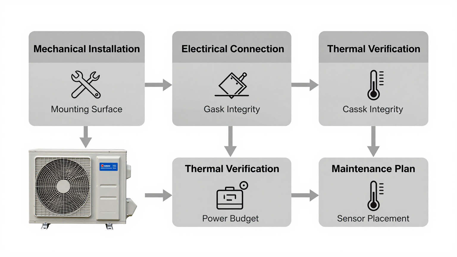
Implementation Checklist: From Installation to Verification
Proper installation is as critical as proper selection. A perfectly sized unit can fail if installed incorrectly. Use this checklist to ensure system integrity.
-
Mechanical Installation
- Mounting Surface: Ensure the mounting surface is flat, rigid, and strong enough to support the unit without vibration.
- Gasket Seal: This is non-negotiable. The gasket between the unit and the enclosure wall must be perfectly compressed to maintain a closed loop and prevent air/water ingress. A compromised seal is a leading cause of a micro dc air conditioner not cooling effectively.
- Airflow Integrity: Confirm that no wires, cables, or components block the internal or external air inlet/outlet paths. Even a partial blockage can cripple performance.
-
Electrical Connection
- Power Budget: Verify the DC power supply can handle the compressor’s startup inrush current, not just its steady-state running current.
- Wire Gauge: Use the manufacturer-recommended wire gauge for the given wire length to prevent voltage drop under load.
- Circuit Protection: Install appropriate fusing or circuit breakers as specified in the installation manual.
-
Thermal Verification
- Sensor Placement: Place the primary control sensor near the top of the enclosure where the hottest air accumulates, but away from the direct cold air outlet. Use additional sensors to monitor critical components and identify potential hotspots.
- Acceptance Test: After installation, run the system under a simulated full thermal load. Measure the internal and ambient temperatures, and the voltage and current at the unit. This data provides a performance baseline for future troubleshooting.
-
Maintenance Plan
- Filter & Fin Cleaning: Establish a regular inspection and cleaning schedule for the condenser and evaporator coils, especially in dusty or oily environments.
- Seal Inspection: Periodically check the integrity of the mounting gasket and any cable glands.
Frequently Asked Questions (FAQ)
Should I choose a larger unit to be safe?
No, this is a common mistake. An oversized unit will short-cycle, leading to poor dehumidification, increased mechanical wear, and inefficient operation. Always perform a proper heat load calculation to select a unit that is correctly sized for the application. A unit that runs for longer, more consistent cycles is more effective and reliable.
What if my enclosure must be IP67 sealed?
This reinforces the need for a closed-loop cooling system like a Micro DC Aircon. The unit itself must be designed to maintain the enclosure’s IP rating. Pay close attention to the mounting gasket system and any electrical or condensate drain connections to ensure they meet the required sealing standards.
How do I manage condensation?
In a properly sealed enclosure with a correctly operating unit, condensation should be minimal as the internal air is dried during the initial cooldown. However, if humid ambient air leaks in, condensation will form on the cold evaporator coil. Most units incorporate a drain port. This must be properly routed to the exterior without compromising the cabinet’s seal.
My system is in direct sun. How does that affect the cooling?
Direct solar radiation adds a significant external heat load. This must be calculated and added to your internal heat load. Using a solar shield or painting the enclosure a light, reflective color can dramatically reduce this load and improve the performance of your cooling system. Ignoring solar gain is a primary reason for a micro dc air conditioner not cooling in outdoor applications.
What is the first thing I must measure when troubleshooting?
Start with the basics. Measure the voltage and current being supplied directly at the unit’s terminals to rule out power issues. Then, measure the temperature of the air entering and leaving both the evaporator (internal) and condenser (external) sides. A small temperature difference across the evaporator (e.g., 2-3°C) often points to low refrigerant or poor airflow.
How can I validate the cooling performance after installation?
The best method is a stress test. Use software to run the internal electronics at 100% load, or use resistive heaters to simulate the total calculated heat load. Let the system run for several hours in the warmest expected ambient conditions and log the internal enclosure temperature. It should stabilize at or below your maximum specified temperature.
Conclusion: From Troubleshooting to Robust Design
When a micro dc air conditioner is not cooling, the problem is rarely the unit itself but rather its integration into the larger system. The core issue in compact system cooling troubleshooting is almost always a miscalculation of the total heat load or a restriction in one of the critical airflow paths. A DC aircon running but no cooling is a clear signal that the system cannot reject heat as fast as it is being generated.
This approach—analyzing the complete thermal circuit, respecting airflow, and calculating all heat loads—is the most effective path to a solution. This methodology works best for sealed enclosures in mobile, outdoor, or high-ambient-temperature environments where maintaining a stable internal environment below ambient is critical. It is less suited for open-frame systems or environments where simple ventilation is sufficient.
If you are facing complex thermal challenges, our engineering team can assist with precise sizing, system integration, and customization for unique mounting, power constraints, or harsh environmental requirements. Contact us to discuss your specific air conditioning project needs.


0 条评论