Angle Lock: The decision is which DC bus voltage—12V, 24V, or 48V—to standardize for a new mobile robotics platform. The primary failure modes to avoid are voltage-drop-induced compressor stalls under peak load and excessive cabling weight that compromises payload capacity. The dominant constraint is the overall system electrical efficiency and battery runtime.
Choosing the Right Bus Voltage for a 12V 24V 48V Micro DC Air Conditioner
Integrating precision climate control into a power-constrained, mobile, or off-grid platform is a significant engineering challenge. For systems like autonomous utility vehicles, mobile sensor pods, or compact electronics enclosures, direct current (DC) powered cooling is non-negotiable. However, the initial choice of system bus voltage—12V, 24V, or 48V—has profound, cascading effects on system performance, reliability, weight, and cost. Making this decision based on component availability alone, rather than system architecture, can lead to costly redesigns and field failures.
An incorrect voltage choice can result in unstable performance, reduced battery life, and wiring harnesses that are impractically heavy and expensive. By the end of this technical analysis, you will be able to confidently select a DC bus voltage for your cooling subsystem based on clear, system-level engineering trade-offs. In this article, we prioritize system-level electrical efficiency and integration reliability over component-level convenience, because a mismatched voltage can undermine the performance of the entire platform.
Deployment Context: Two Real-World Scenarios
The choice of bus voltage is rarely made in a vacuum. It is dictated by the constraints of the application and the overall system design philosophy.
Scenario A: Retrofitting an Agricultural Drone with a 12V System
An engineering team was tasked with adding a thermally sensitive hyperspectral imaging payload to an existing agricultural drone. The drone’s architecture was built on a 12V bus, chosen for its compatibility with a wide range of off-the-shelf cameras and GPS modules. When they added a compact DC air conditioner to cool the sensor, they encountered intermittent compressor startup failures during high ambient temperatures. The root cause was excessive voltage drop across the long, thin wire run from the central power distribution board to the payload wing, a problem magnified by the high current draw of the 12V cooling unit.
Scenario B: Designing a New 48V Light Electric Vehicle
A startup was developing a new light-electric utility vehicle for logistics and campus maintenance. The design team selected a 48V electrical architecture from the outset to maximize the efficiency of the traction motor and minimize the weight of the main power cabling. For cooling the sealed motor controller and battery management system (BMS) cabinet, they initially considered using a common 12V air conditioner powered by a step-down DC-DC converter. However, their analysis showed that the 5-10% efficiency loss in the converter, plus the added heat load from the converter itself, made a native 48V cooling solution a far more reliable and efficient choice.
Common Failure Modes & System Constraints
When integrating a DC-powered vapor-compression cooling system, the electrical interface is a primary source of risk. The following issues, ranked by impact, often stem from a suboptimal voltage choice:
- Voltage Drop → Compressor Stall → Insufficient voltage at the unit’s terminals under load prevents the compressor from starting, leading to shutdown and loss of cooling.
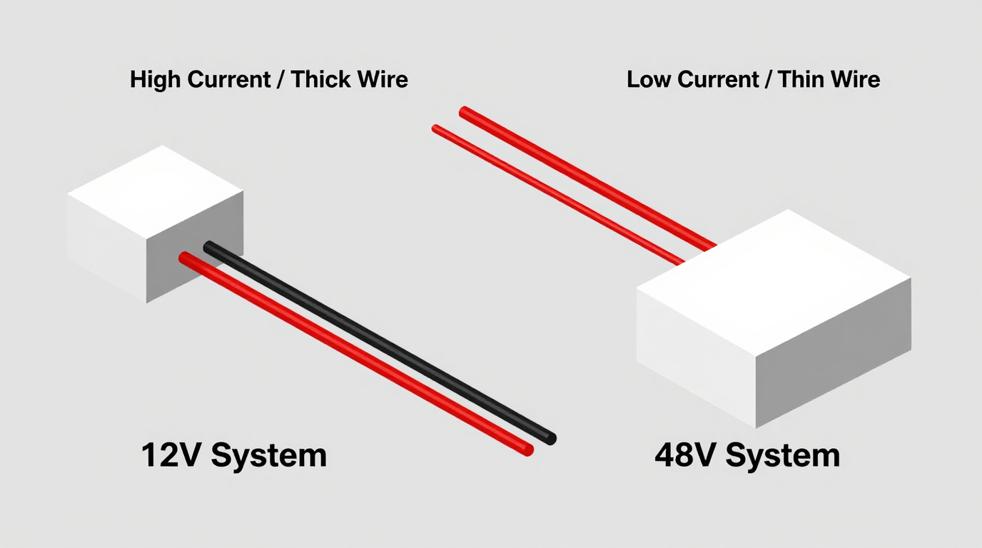
- High Current Draw → Oversized Wiring → Low-voltage (12V) systems require thick, heavy, and expensive copper cables to manage high amperage, complicating routing in space-constrained designs.
- Converter Inefficiency → Wasted Battery Life → Using a DC-DC converter to step voltage down (e.g., 48V to 12V) introduces an efficiency loss of 5-15%, draining the battery faster and generating waste heat.
- Mismatched Bus → Increased Complexity → Adding converters creates more points of failure, requires additional fusing, and complicates system diagnostics.
- Inrush Current Sag → Bus Instability → The high initial current needed to start a compressor can cause a momentary voltage dip that resets or disrupts other sensitive electronics on the same bus.
- High-Current Connections → Thermal Risk → Poorly crimped or loose connectors in a high-current 12V system can generate significant heat, posing a fire risk and a point of failure.
- Battery Discharge Curve → Performance Degradation → As a battery discharges, its terminal voltage drops. This effect is more pronounced in 12V systems, potentially leading to premature low-voltage cutoffs for the cooling unit.
Engineering Fundamentals: Power, Current, and Voltage
The core of the voltage selection decision lies in the fundamental relationship: Power = Voltage × Current. For a Micro DC Aircon with a fixed cooling capacity, the required electrical power (in Watts) is relatively constant. This means that as you increase the system voltage, the required current (in Amps) decreases proportionally.
For example, a cooling unit requiring 480 Watts of electrical power would draw:
- 40 Amps at 12V
- 20 Amps at 24V
- 10 Amps at 48V
This inverse relationship is critical because of electrical resistance. All wires have some resistance, which causes power loss in the form of heat, governed by the formula P = I²R (Power Loss = Current Squared × Resistance). Because the current is squared, its impact on power loss is exponential. Halving the current (by doubling the voltage) reduces the resistive power loss in the wiring by a factor of four. This is the primary reason why higher voltage systems are more efficient for distributing significant power.
Common Misconception: “A 12V system is always simpler and cheaper because 12V components are widely available.”
Engineering Correction: This is true for low-power components like lights and sensors. For high-power devices like a 12v 24v 48v micro dc air conditioner (drawing 100W to 900W), a higher native voltage (24V or 48V) creates a far simpler and more robust system. It dramatically reduces the challenges of managing high current, allowing for thinner, lighter, and less expensive wiring, smaller connectors, and improved overall system efficiency, which translates directly to longer battery runtime.
Specifications for Micro DC Aircon Series
The decision to use a specific voltage is an electrical architecture choice, not a thermal one. As shown in the table below, for a given cooling capacity, multiple voltage options are often available. The key is to select the model that aligns with your system’s native bus voltage to maximize efficiency and reliability. These specifications represent common configurations; custom solutions are also possible.
| Model (Example) | Voltage (VDC) | Nominal Cooling Capacity (W) | Refrigerant |
|---|---|---|---|
| DV1910E-AC (Pro) | 12V | 450W | R134a |
| DV1920E-AC (Pro) | 24V | 450W | R134a |
| DV1930E-AC (Pro) | 48V | 450W | R134a |
| DV3220E-AC (Pro) | 24V | 550W | R134a |
Engineering Selection Matrix: Logic Gates for Voltage Choice
To make a defensible engineering decision, pass your project requirements through these three logic gates. The outcome will point toward the most robust voltage architecture.
1. The Legacy System Gate: Integrating with an Existing Bus
- Constraint Gate: You are integrating the cooling unit into a pre-existing platform (e.g., a commercial vehicle, an existing drone model) with a fixed and validated 12V or 24V electrical system.
- Decision Trigger: If the platform’s power source is a 12V or 24V alternator, or if changing the entire system’s bus voltage is not feasible due to cost, schedule, or validation constraints.
- Engineering Resolution: Select a Micro DC Aircon model that matches the native bus voltage. For a 12V system, this means accepting the high current draw as a known constraint.
- Integration Trade-off: This path requires rigorous analysis of the power delivery network. You must use a voltage drop calculator to specify a heavy-gauge wire sufficient to keep the voltage at the unit’s terminals within its operating range (typically +/- 10%) at full load. Fuses, relays, and connectors must all be rated for the high continuous amperage (e.g., 35-45A for a 450W unit at 12V).
2. The Greenfield Efficiency Gate: Designing a New Battery-Powered System
- Constraint Gate: You are designing a new, electrically powered system from a clean sheet, where overall energy efficiency and battery runtime are the most critical performance metrics.
- Decision Trigger: If the system includes other high-power components (motors, actuators, high-power computing) and the total power budget is a primary design driver.
- Engineering Resolution: Default to the highest practical voltage, which is typically 48V for systems of this scale. This choice minimizes I²R (resistive) losses throughout the entire power distribution harness, not just for the cooling subsystem.
- Integration Trade-off: While the high-power components benefit greatly, you may need small, efficient point-of-load DC-DC converters to power low-voltage ancillary components like sensors or microcontrollers. However, this trade-off is almost always worth the significant improvement in overall system efficiency and the reduction in high-current cabling weight and cost.
3. The Power-Over-Distance Gate: Managing Long Cable Runs
- Constraint Gate: The physical distance between the power source (battery, power distribution unit) and the location of the cooling unit is significant, typically more than 2-3 meters.
- Decision Trigger: If a voltage drop calculation for a 12V implementation shows a drop greater than 3-5% under full load, which would place the input voltage dangerously close to the unit’s low-voltage cutoff threshold.
- Engineering Resolution: Mandate the use of a 24V or 48V system. For the same power delivery and percentage voltage drop, a 48V system requires a wire with only 1/16th the cross-sectional area of a 12V system. This makes the wiring harness substantially lighter, more flexible, and less expensive.
- Integration Trade-off: The decision is effectively forced by physics. Attempting to use a 12V system in this scenario would result in unreliable performance or require an impractically thick and heavy cable, compromising the entire mechanical design. The choice of a 12v 24v 48v micro dc air conditioner becomes a tool to solve a system-level physics problem.
Implementation & Verification Checklist
After selecting the appropriate voltage, successful integration depends on disciplined implementation and verification.
- Electrical System Validation
- Power Source Capability: Confirm your battery or power supply can deliver the required continuous current and handle the brief inrush current of the compressor motor without its voltage collapsing below the unit’s minimum threshold.
- Wire Gauge Calculation: Do not guess. Use an AWG wire gauge chart and a voltage drop calculator. Input your maximum current, total wire length (positive + negative lead), and specify a maximum acceptable drop of 3%.
- Overcurrent Protection: Install a correctly rated fuse or circuit breaker (e.g., MIDI or MAXI fuse for higher currents) as close to the power source as possible to protect the wiring.
- Mechanical Integration
- Vibration Damping: In mobile applications, mount the unit using vibration-damping grommets or brackets to protect the compressor and refrigerant lines.
- Airflow Integrity: Ensure the condenser and evaporator air streams are physically separated. Never allow hot air exhausting from the condenser to be drawn back into the condenser inlet, as this will severely degrade performance.
- Enclosure Sealing: When cooling a sealed enclosure, ensure all mounting hardware and cable pass-throughs are properly gasketed to maintain the desired IP rating.
- Thermal Performance Verification
- Correct Sensor Placement: Place your control thermocouple on the critical component being cooled or in the return air path, not directly in the cold output stream of the evaporator.
- Soak and Load Test: Perform a system-level test by allowing the entire assembly to “soak” at the maximum expected ambient temperature and then operate it under the maximum thermal load to verify it can maintain the target temperature indefinitely.
Frequently Asked Questions (FAQ)
Can’t I just use a DC-DC converter to run a 12V unit on my 48V system?
You can, but it is not recommended for high-power loads. You introduce a component that is an additional point of failure, suffers from 5-15% efficiency loss (wasting battery life), and generates its own waste heat that must be managed within your electronics enclosure.
What is the real-world impact of excessive voltage drop?
It causes a progressive loss of cooling capacity as the compressor and fan speeds decrease. In a worst-case scenario, the voltage at the unit sags below the control board’s low-voltage cutoff threshold during compressor startup, leading to repeated failed starts or a complete shutdown.
Does a 48V micro DC air conditioner cool more effectively than a 12V version?
No. For a given model series with the same cooling capacity rating (e.g., 450W), the thermal performance is identical. The voltage options relate to electrical system efficiency and integration, not the refrigeration cycle’s capacity.
Are there significant safety differences between 12V, 24V, and 48V?
All three are considered Safety Extra-Low Voltage (SELV) in many contexts, making them generally safer than high-voltage AC. However, 48V systems (which can have open-circuit voltages exceeding 55V) demand more stringent practices for insulation, connector shrouding, and short-circuit protection to mitigate arc flash risks.
How do I definitively choose the right wire size for my 12v 24v 48v micro dc air conditioner?
Use a standard voltage drop calculator. You will need three inputs: the maximum current draw of the unit (from its datasheet), the total length of the wire run (from the power source to the unit and back), and your desired maximum voltage drop (3% is a safe target). The calculator will recommend the appropriate wire gauge (AWG or mm²).
My power source is a vehicle alternator. How does that affect my choice?
In this case, you should almost always match the vehicle’s native bus voltage. Most light vehicles use 12V, while many heavy-duty trucks and equipment use 24V. Using a unit with a matching native voltage eliminates the need for power converters, which are often failure points in high-vibration environments.
Conclusion: A System-Level Decision
The selection of a 12v 24v 48v micro dc air conditioner is fundamentally a decision about your entire electrical architecture. The voltage is not just another spec on a datasheet; it is the constraint that dictates wire harness design, system efficiency, and ultimately, operational reliability.
For new, battery-dependent systems where performance and runtime are paramount, a 48V architecture offers undeniable advantages in efficiency and weight savings. For integrations into existing vehicles or platforms with a fixed bus voltage, matching the native 12V or 24V system is the most practical approach, provided that the high current and potential for voltage drop are meticulously managed through proper engineering.
If you are designing a system with challenging power constraints, a high-vibration environment, or a unique enclosure geometry, our engineering team can assist in sizing and customizing a Micro DC Aircon solution that aligns with your specific architectural needs.


0 条评论