Angle: The critical decision is how to correctly size a battery bank and solar array for an off-grid cooling system. The most common failure modes are battery depletion leading to thermal shutdown and an undersized solar array causing cascading power failure over several days. The dominant constraint is the total energy power budget, balancing peak demand, operational duty cycle, and the solar recharge window.
Powering Remote Electronics: A Guide to Micro DC Air Conditioner Battery Sizing
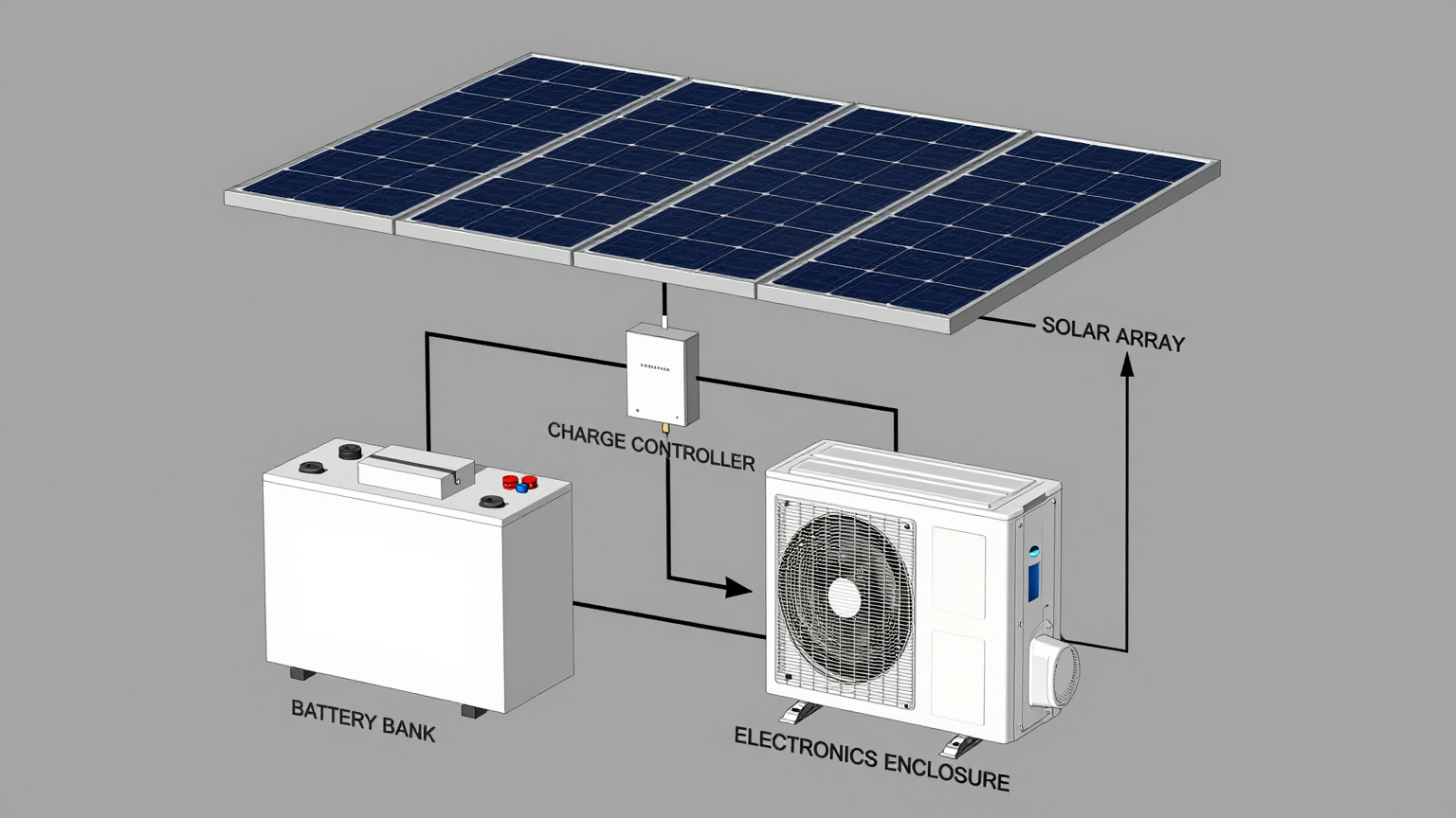
A remote telecom cabinet goes offline. The cause isn’t a network failure or a software bug; it’s heat. The battery bank powering the enclosure’s cooling unit was undersized, and after two cloudy days, it depleted, shutting down the air conditioner. Inside, sensitive radio equipment quickly exceeded its maximum operating temperature, leading to a costly service outage and a multi-thousand-dollar truck roll to a remote site. This scenario is a common and entirely preventable failure in off-grid and mobile systems. The root cause is almost always an incomplete power budget that overlooks the real-world operational dynamics of the thermal management system.
Simply matching a cooling unit’s peak power rating to a battery and solar panel is a recipe for failure. A reliable system depends on a much deeper analysis of energy consumption over time. By the end of this technical guide, you will be able to construct a robust off-grid enclosure cooling power budget, ensuring your critical electronics remain cool and operational, regardless of location. In this article, we prioritize real-world power consumption and duty cycle analysis over nominal spec sheets, because off-grid survival depends on managing energy over time, not just peak performance.
Deployment Context: Where Power Planning is Mission-Critical
Theoretical calculations fall short when faced with real-world environmental challenges. Consider these two common scenarios where a detailed power budget is the difference between reliability and recurring failure.
Scenario A: Remote Telecom Repeater Station
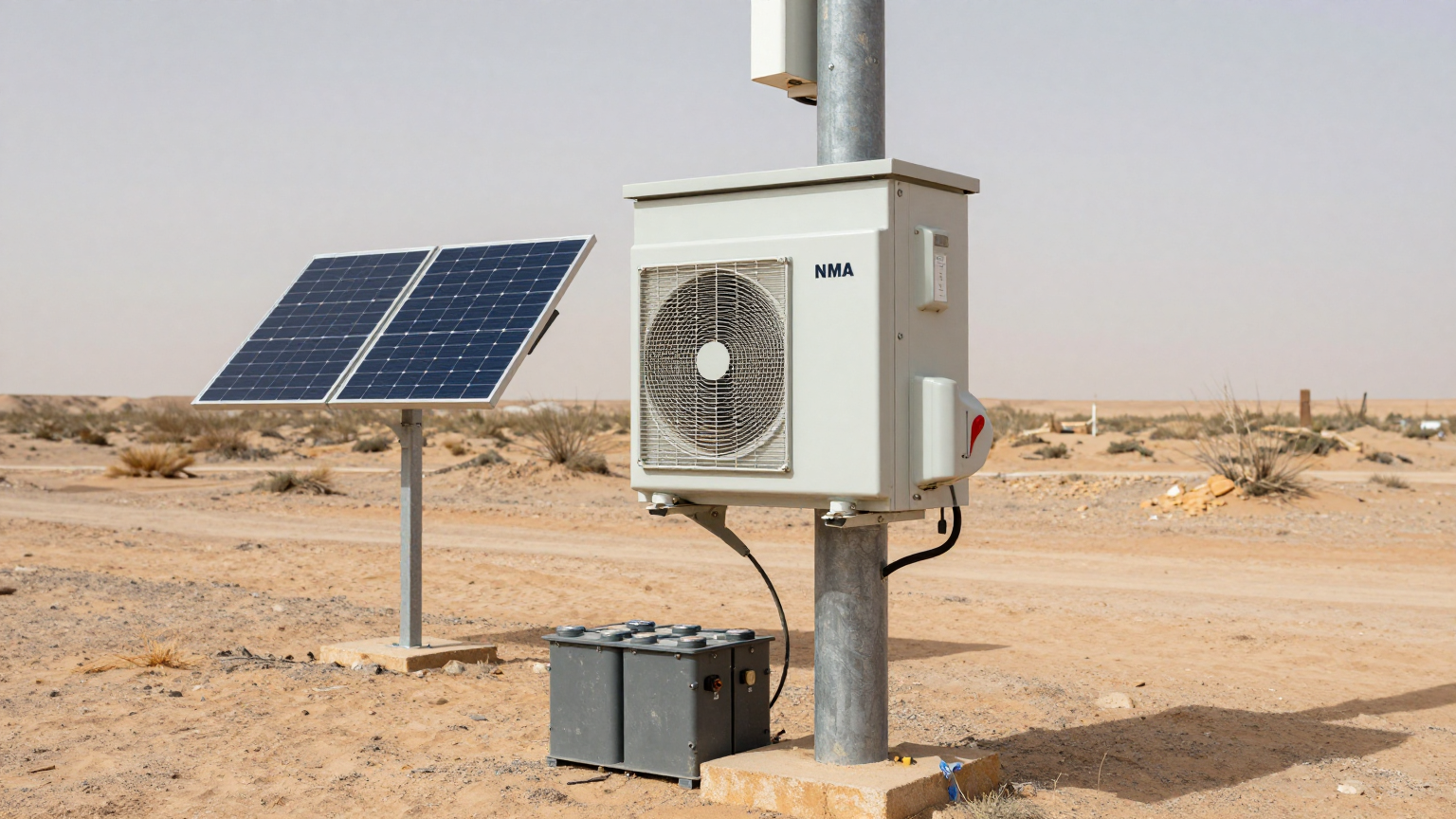
A 5G network provider deploys repeater nodes in a desert region to expand rural coverage. The sealed NEMA enclosures protect sensitive RF equipment. Initially, they used high-flow fans, but these failed when summer ambient temperatures consistently exceeded 45°C, causing the internal electronics to derate and drop service. The switch to active cooling is necessary, but the primary constraint is energy autonomy. The system must guarantee 100% uptime, which requires a power system capable of running the cooling unit through at least three consecutive days of sandstorms or heavy cloud cover with zero solar input. This is a classic challenge in telecom components cooling where reliability is paramount.
Scenario B: Mobile SCADA Monitoring Unit
An energy company uses mobile trailers equipped with SCADA systems to monitor pipeline integrity in remote locations. These units house control PLCs, sensors, and communication hardware that must be protected from both heat and dust. The previous thermoelectric coolers were inefficient and struggled to handle the high solar load on the trailer’s metal skin. The key constraint here is the limited physical footprint. There is a finite amount of roof space for a solar powered dc air conditioner module and limited chassis space for a battery bank, placing a premium on the cooling unit’s energy efficiency to minimize the size and weight of the required power system.
Common Failure Modes & System Constraints
When designing an off-grid cooling system, engineers must anticipate potential points of failure. These issues typically cascade, starting with a power deficit that leads to a thermal event. Here are the most common failure modes, ranked by impact:
- System Shutdown from Battery Depletion → Undersized battery bank or an incorrectly configured low-voltage disconnect (LVD) → Leads to a complete thermal management failure and potential damage to the battery itself.
- Progressive Loss of Autonomy → Undersized solar array or suboptimal panel orientation → The battery never fully recharges each day, leading to a system failure after a few cloudy days.
- Premature Compressor Failure → Cooling unit short-cycling due to insufficient voltage from the battery under load → Causes excessive wear on the compressor and wastes energy.
- Cooling Unit Starvation → Excessive voltage drop caused by inadequate DC wire gauge over a long run → The control board receives insufficient voltage and shuts down the compressor, even if the battery is charged.
- Thermal Runaway Event → The power system fails, the cooling unit stops, and the enclosure’s internal heat load and solar gain cause temperatures to rise uncontrollably → Results in catastrophic, often permanent, damage to the protected electronics.
- Nuisance Breaker/BMS Trips → Sizing the power system for the average load but ignoring the compressor’s higher startup inrush current → The Battery Management System (BMS) or circuit protection disconnects the load, causing intermittent shutdowns.
Engineering Fundamentals: Beyond Peak Watts to Watt-Hours
The core of a successful off-grid power system is the energy budget, measured in Watt-hours (Wh). This budget quantifies the total amount of energy the cooling system will consume in a 24-hour period and the total energy the solar array must generate to replenish it. Three concepts are fundamental to building this budget.
1. Duty Cycle: The Most Important Variable
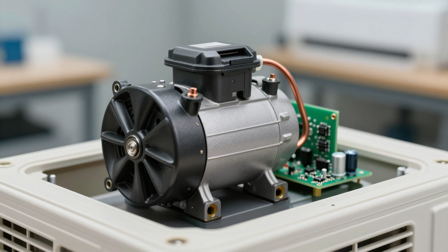
The duty cycle is the percentage of time the air conditioner’s compressor is actively running. A cooling unit in a hot, poorly insulated enclosure might run 80% of the time (80% duty cycle). The same unit in a well-insulated enclosure with a lower heat load might only run 20% of the time. This single factor is the most powerful lever in your power budget. A Micro DC Aircon with its variable-speed compressor is highly efficient because it can ramp down its speed to precisely match a low thermal load, further reducing average power consumption compared to a simple on/off system. Calculating the daily energy need based on 100% runtime is the most common and costly mistake in system sizing.
2. Peak Sun Hours: Your Recharge Window
This term does not refer to the number of daylight hours. It represents the equivalent number of hours per day when solar irradiance is at its peak (1,000 W/m²). A location might have 12 hours of daylight but only 4.5 Peak Sun Hours. This value, which varies by geographic location and season, determines how large your solar array must be to fully recharge the battery each day. Always design for the worst-case scenario, typically the winter months when Peak Sun Hours are at their lowest.
3. Battery Autonomy: Planning for Bad Weather
Autonomy is the number of days your system can operate without any solar input. For mission-critical applications, planning for 3 to 5 days of autonomy is standard practice. This means the battery bank must be large enough to store three to five times your calculated daily energy consumption, providing a crucial buffer against extended periods of poor weather.
A common misconception is believing you can size the power system using the cooling unit’s maximum power rating. This approach results in a grossly oversized and prohibitively expensive battery and solar array. The correct method involves calculating the *average* power consumption by multiplying the unit’s running power draw by the expected duty cycle. This yields the total energy (in Watt-hours) needed per day, which is the true foundation of your micro dc air conditioner battery sizing plan.
Specification Gateway for Power Budgeting
Before creating a power budget, you must start with the manufacturer’s verified specifications. The table below outlines baseline parameters for the Rigid Chill Micro DC Aircon series. When planning your system, the critical first step is to match the unit’s nominal voltage to your chosen battery bank architecture (e.g., 12V, 24V, or 48V). The cooling capacity helps determine the duty cycle against your thermal load, but the actual power draw will be variable, managed by the inverter to maximize efficiency.
| Model (Example) | Voltage (VDC) | Nominal Cooling Capacity (W) | Refrigerant |
|---|---|---|---|
| DV1910E-AC (Pro) | 12V | 450W | R134a |
| DV1920E-AC (Pro) | 24V | 450W | R134a |
| DV1930E-AC (Pro) | 48V | 450W | R134a |
| DV3220E-AC (Pro) | 24V | 550W | R134a |
Engineering Selection Matrix: Power Sizing Logic Gates
A robust power system is designed by passing through a series of logical gates. Each gate addresses a specific constraint and forces a clear engineering decision, moving from the thermal challenge to the final hardware selection.
Logic Gate 1: Estimate the Thermal Load & Duty Cycle
- Constraint Gate: Total Heat Load (from internal electronics plus external solar gain) versus the Enclosure’s Thermal Resistance (insulation properties).
- Decision Trigger: The calculation of the approximate runtime required to hold the desired internal temperature. For example, if the total continuous heat load is 150W and you select a 450W cooling unit, the theoretical duty cycle will be around 33% (150W / 450W).
- Engineering Resolution: This estimated duty cycle becomes the primary multiplier for your entire energy budget. Reducing the duty cycle through better insulation or sun shielding is the most effective way to shrink the required power system.
- Integration Trade-off: Adding insulation or a physical sun shield to the enclosure increases upfront mechanical cost and complexity but provides a massive return by directly reducing the cooling duty cycle, which in turn lowers the required battery and solar capacity.
Logic Gate 2: Calculate the Daily Energy Budget (Watt-Hours)
- Constraint Gate: The cooling unit’s average power draw while running versus a 24-hour operational cycle.
- Decision Trigger: If a 24V Micro DC Aircon (like the DV1920E-AC Pro example) draws an average of 240 Watts while the compressor is active, and your estimated duty cycle is 40% (equivalent to 9.6 hours of total runtime per day)…
- Engineering Resolution: …the daily energy consumption is 240 Watts × 9.6 hours = 2,304 Watt-hours (Wh). This is the minimum amount of energy your solar array must generate and your battery must store for one day of operation. This is the heart of the off-grid enclosure cooling power budget.
- Integration Trade-off: Selecting a high-efficiency, variable-speed DC compressor system over a less expensive on/off or thermoelectric unit results in a lower average power draw for the same amount of cooling, directly reducing the required daily Watt-hours and the cost of the entire power system.
Logic Gate 3: Define Battery Capacity & Autonomy
- Constraint Gate: The Daily Energy Budget versus the required number of Days of Autonomy (no-sun days).
- Decision Trigger: If the daily energy need is 2,304 Wh and the operational requirement demands 3 days of autonomy…
- Engineering Resolution: …the minimum *usable* battery capacity is 2,304 Wh/day × 3 days = 6,912 Wh. To prevent damage, you must also account for the battery’s maximum depth-of-discharge (DoD). For a LiFePO4 battery with a 90% DoD limit, the total required capacity is 6,912 Wh / 0.90 = 7,680 Wh. For a lead-acid battery with a 50% DoD limit, this balloons to 13,824 Wh.
- Integration Trade-off: LiFePO4 batteries have a higher initial cost per Watt-hour but offer a much smaller, lighter footprint and longer cycle life for the same usable capacity. This makes them the superior choice for mobile or space-constrained applications.
Logic Gate 4: Size the Solar Array for Recharge
- Constraint Gate: The Daily Energy Budget (plus system losses) versus the location’s worst-case Peak Sun Hours.
- Decision Trigger: If the system needs to replenish 2,304 Wh daily, and we add 20% to account for charging inefficiency and system losses (totaling ~2,765 Wh), and the location provides only 3.5 Peak Sun Hours in winter…
- Engineering Resolution: …the minimum required solar array size is 2,765 Wh / 3.5 hours = 790 Watts. This calculation ensures the array can fully recharge the battery even on the shortest, darkest days of the year. This completes the plan for a truly reliable solar powered dc air conditioner module.
- Integration Trade-off: Oversizing the solar array by 20-25% (e.g., to 1,000W) provides a critical buffer against panel soiling, degradation over time, and less-than-perfect weather conditions. This modest upfront investment significantly improves long-term system resilience and battery health.
Implementation & Verification Checklist
Proper design must be followed by meticulous implementation. Use this checklist to ensure the system you designed on paper performs reliably in the field.
- Pre-Installation System Audit
- Confirm your thermal load calculations. If possible, perform a test run of the electronics in a controlled environment to measure their actual heat output.
- Use a trusted tool like the NREL PVWatts Calculator to verify the Peak Sun Hours for your specific deployment location and panel orientation.
- Finalize battery chemistry (e.g., LiFePO4, AGM) and confirm the voltage of all components (panels, charge controller, battery, cooling unit) are compatible.
- Mechanical Installation
- Mount the Micro DC Air Conditioner to ensure unobstructed airflow for both the condenser (hot side) and evaporator (cold side).
- Meticulously seal all cable glands, mounting holes, and door gaskets on the enclosure to prevent air leakage, which would increase the thermal load and cooling duty cycle.
- Ensure solar panels are securely mounted and oriented for optimal solar exposure, accounting for the sun’s path in the critical season (usually winter).
- Electrical Commissioning
- Use a voltage drop calculator to select the correct wire gauge for the DC power run between the battery bank and the air conditioner. Undersized wires will starve the unit of power.
- Install correctly rated fuses or circuit breakers as close to the battery’s positive terminal as possible to protect the system.
- Program the solar charge controller and/or Battery Management System (BMS) with the correct parameters for your battery, especially the high and low voltage disconnect setpoints.
- Thermal Performance Validation
- Place a temperature data logger inside the enclosure, away from the direct cold air stream, to record the true average internal ambient temperature.
- Allow the system to run for at least 48 hours, monitoring the battery’s state of charge and the cooling unit’s on/off cycles to validate that your real-world duty cycle matches your design estimates.
Frequently Asked Questions (FAQ)
How do I estimate the cooling duty cycle without building a prototype?
Start with a detailed thermal calculation. Sum the heat output (in watts) of all internal components. Use an online calculator to estimate the solar gain on your enclosure’s outer surfaces based on its size, color, and location. Add these together for your total heat load. Divide this by the cooling capacity of the air conditioner to get a baseline duty cycle, then add a 25% safety margin.
Should I choose a 12V, 24V, or 48V system?
For new system designs, 48V is often the superior choice. Higher voltage results in lower current (Amps) for the same amount of power, which allows for smaller, less expensive wiring and reduces energy loss from voltage drop. If you are integrating with an existing power system (e.g., on a vehicle), match the existing nominal voltage.
What is more important: a bigger battery or more solar panels?
They solve two different problems. The battery provides autonomy—the ability to survive without sun. The solar panels provide the daily recharge. An undersized battery means you can’t survive a few cloudy days. An undersized solar array means your battery will slowly drain even on sunny days. A successful micro dc air conditioner battery sizing project requires both to be sized correctly and in balance.
How does direct sun on the enclosure affect my power budget?
It has a massive impact. A dark-colored metal enclosure sitting in direct sun can experience a solar heat gain of over 1,000 Watts per square meter. This adds directly to your thermal load, forcing the cooling unit to run far more often. A simple, inexpensive sun shield or painting the enclosure a reflective white color can drastically reduce solar gain, lowering the duty cycle and your overall power requirements.
Can I run a Micro DC Air Conditioner directly from a solar panel?
No. A vapor-compression air conditioner requires a stable DC voltage source capable of handling the compressor’s inrush current. The output of a solar panel is highly variable. A battery bank is essential to act as a stable power buffer between the panels and the cooling unit.
What is the single most important measurement I must take first?
The two most critical inputs are the maximum continuous heat output (in watts) of the electronics you are protecting and the highest ambient temperature the enclosure will experience at the deployment site.
Conclusion: From Budgeting to Reliability
A successful off-grid thermal management system is, first and foremost, a successful energy management system. By shifting the focus from peak power ratings to a comprehensive 24-hour energy budget, system designers can move beyond guesswork and build solutions that are both cost-effective and exceptionally reliable. This data-driven approach—balancing thermal load, duty cycle, battery autonomy, and solar recharge capacity—is the only way to guarantee that sensitive electronics remain protected in demanding remote environments.
This methodology for creating an off-grid enclosure cooling power budget is most critical for any mobile or remote application where grid power is unavailable and system reliability is non-negotiable. A precise power plan depends on many project-specific variables. If you are designing a system with unique constraints—such as high-altitude operation, corrosive salt-fog environments, or non-standard power sources—contact our engineering team to discuss custom configurations and detailed thermal analysis for your project.


0 条评论