For reliability engineers and system integrators, the gap between a datasheet and a deployed reality is often where failure occurs. You can select a cooling unit with the perfect BTU rating, but if the integration into the sealed enclosure ignores the physics of the field environment, the system will overheat. This is particularly true for active cooling solutions like miniature vapor-compression systems, where airflow paths, power stability, and sealing integrity interact in complex ways.
Executing a robust micro dc air conditioner validation test before mass deployment is the only way to close this gap. It does not always require a climate chamber. In fact, bench testing and field simulation often reveal integration flaws that a sterile lab environment hides, such as cable gland leaks, battery voltage sag under load, or short-cycling due to poor sensor placement.
This guide outlines a practical, consultant-style test plan for validating Micro DC Aircon integrations in harsh, off-grid, or mobile environments. We focus on what you can measure with standard tools—thermocouples, multimeters, and thermal cameras—to ensure your expensive electronics remain safe.
The High Stakes of Sealed Enclosure Cooling
When building for outdoor, remote, or mobile applications, the constraints are severe. You are likely dealing with high ambient temperatures (often exceeding 45°C), limited power budgets (solar/battery), and the absolute necessity of keeping contaminants out. A standard fan-and-filter approach fails because it relies on ambient air exchange; if the air is hot or dusty, the electronics suffer.
Active cooling using a Micro DC Aircon (vapor-compression) is often the solution, but it introduces new variables. The compressor needs stable DC power. The evaporator produces condensate that must be managed. The condenser rejects heat that must not recirculate. A validation plan must verify these interactions, not just the cooling unit itself.
Deployment Context: Where Theory Meets Reality
To understand why a specific micro dc air conditioner validation test protocol is necessary, consider these two common deployment scenarios where “standard” testing often misses the mark.
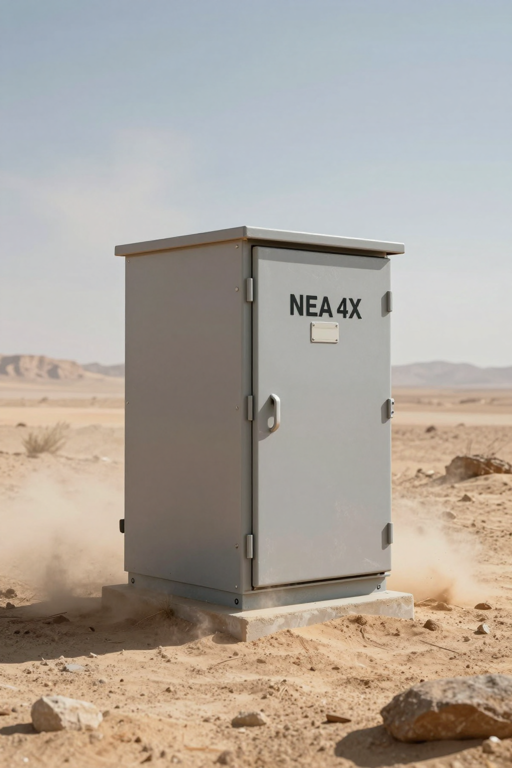
Scenario A: The Solar-Powered Telecom Node
A remote LTE repeater is housed in a NEMA 4X cabinet in a desert environment. The system relies on a 48V battery bank charged by solar panels.
The Constraint: The cooling unit must operate most aggressively when the sun is hottest (peak load), which coincides with the highest battery charging current. However, at night, the unit must cycle efficiently to avoid draining the battery reserves.
The Risk: If the validation test doesn’t account for voltage drop over long cable runs, the compressor’s under-voltage protection might trigger prematurely during compressor startup (inrush), causing the system to shut down exactly when cooling is needed most.
Scenario B: Mobile Medical Transit Case
A ruggedized server case for emergency medical response is deployed in humid, tropical zones.
The Constraint: The system is frequently moved, subjected to vibration, and powered by vehicle DC (12V or 24V) or temporary generators.
The Risk: High humidity leads to rapid condensate generation. If the drain line is not validated for tilt angles or if the evaporation tray is undersized, water will pool inside the sealed electronics compartment, causing catastrophic short circuits.
Decision Matrix: Selecting the Right Cooling Architecture
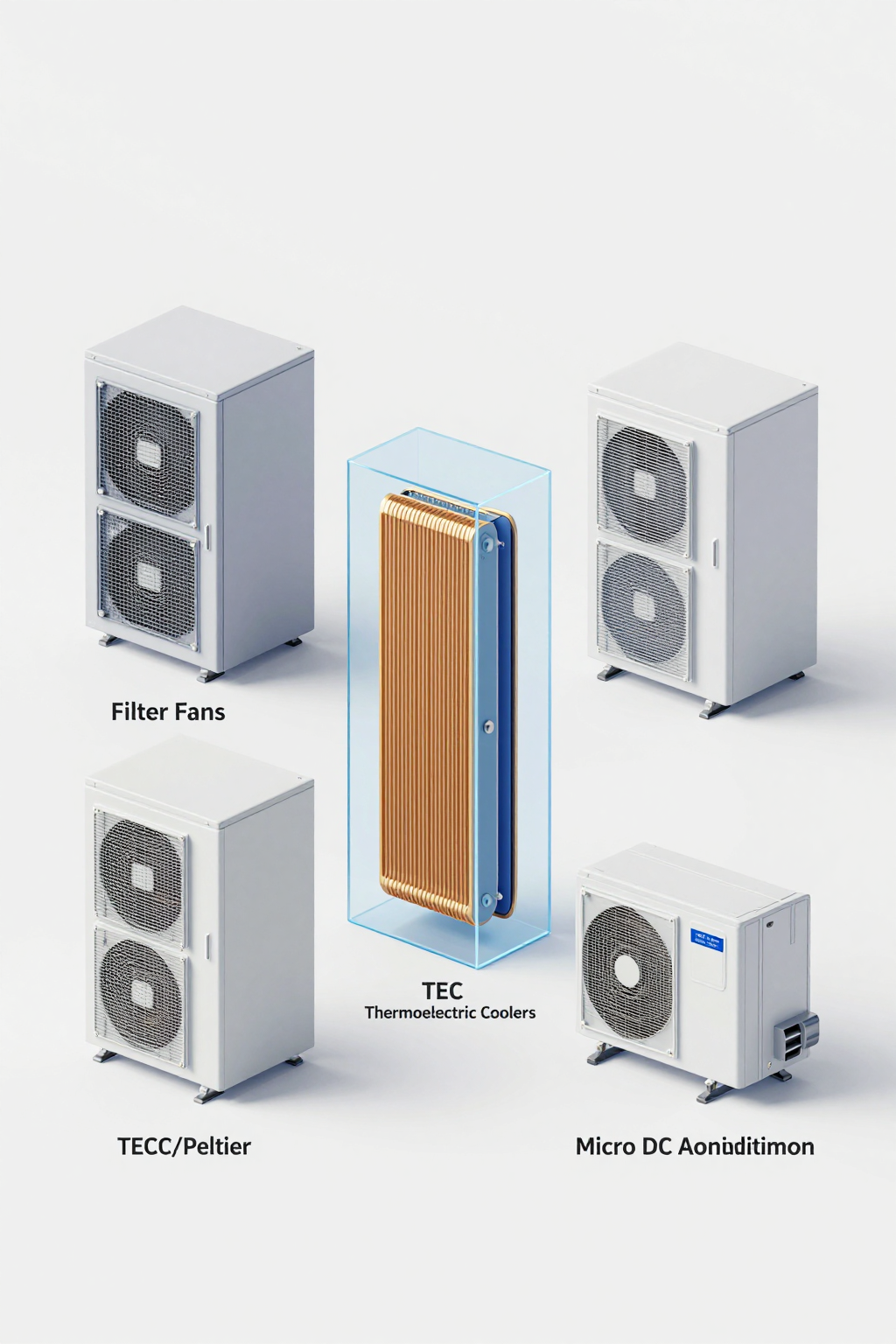
Before finalizing your test plan, confirm that you have selected the correct technology. Engineers often debate between simple fans, Thermoelectric Coolers (Peltier), and Micro DC Air Conditioners. Here is how they compare in harsh deployment contexts.
| Criteria | Filter Fans (Open Loop) | Thermoelectric (TEC/Peltier) | Micro DC Aircon (Compressor) |
|---|---|---|---|
| Sub-Ambient Cooling | Impossible (Always > Ambient) | Yes (Limited Delta T) | Yes (High Delta T) |
| Sealing (IP/NEMA) | Low (Dust/Moisture Ingress) | High (Closed Loop) | High (Closed Loop) |
| Cooling Capacity | Low to High (Depends on Airflow) | Low (< 200W typically) | Medium/High (100W–900W+) |
| Efficiency (COP) | High (Fans only) | Very Low (COP < 0.6) | High (COP > 2.5 – 3.0) |
| Maintenance | High (Filter cleaning) | Low (Solid state) | Low (No filters to clog) |
| Best Fit | Indoor / Clean / Cool Ambient | Small Enclosures / Low Heat Load | High Heat / Solar / Harsh Outdoor |
Implication: If your application requires sub-ambient cooling (keeping internals at 25°C when outside is 45°C) and high efficiency to save battery life, the Micro DC Aircon is typically the only viable physics-based solution. TECs consume too much power for the cooling they provide in these ranges.
Quick Selection Rules for Design Review
- If the ambient temperature exceeds the target internal temperature, then open-loop fans will physically fail to cool the equipment.
- If the power source is battery/solar, then verify the Coefficient of Performance (COP). A compressor-based system typically delivers 3W of cooling for every 1W of power, whereas TECs often use 1W of power for 0.5W of cooling.
- If the enclosure must be NEMA 4/IP65, then you must use a closed-loop solution (TEC or DC Aircon) to prevent contaminant ingress.
- If the heat load exceeds 300W, then TECs usually become cost-prohibitive and power-inefficient compared to a Micro DC Aircon.
- If vibration is a factor, then ensure the compressor is mounted with appropriate rubber isolation grommets (standard on most Micro DC units).
Unseen Enemies of Uptime: Failure Modes
Why do we test? Because the datasheet assumes a perfect world. In a real deployment, several “invisible” factors can degrade performance. A proper micro dc air conditioner validation test is designed to expose these specific failure modes.
- Thermal Short-Cycling: If the cool air from the air conditioner is blown directly into its own intake sensor (due to poor ducting or tight spacing), the unit will think the cabinet is cold and turn off. Minutes later, it heats up and turns on. This rapid cycling kills efficiency and stresses the compressor.
- Condensate Overflow: In high humidity, a 450W cooling unit can generate significant moisture. If the drain line is pinched, clogged, or routed uphill, water backs up into the electronics.
- Inrush Current Trips: DC compressors have a startup surge. If your power supply or wiring is undersized, the voltage may dip below the “Low Voltage Cutoff” threshold during startup, causing the controller to reset endlessly.
- Solar Gain Overload: Engineers often calculate internal heat load but forget the sun. Direct solar loading on a grey cabinet can add 200W–300W of heat, pushing the system beyond its capacity.
Engineering Fundamentals: The Physics of Sealed Cooling
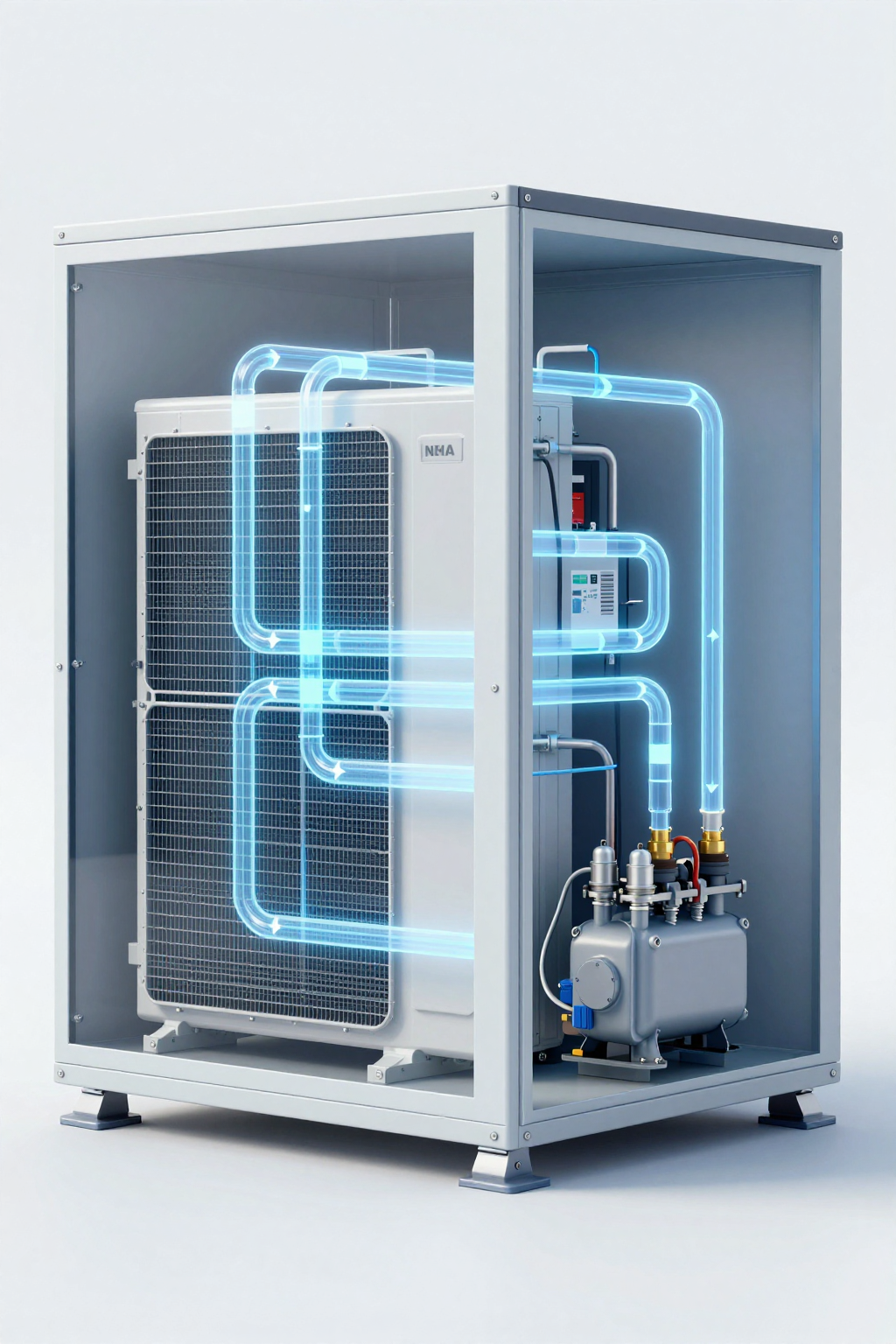
To validate the system, you must understand what is happening thermodynamically. A Micro DC Aircon operates on a vapor-compression cycle. It does not “make cold”; it moves heat. It absorbs heat from the internal air (evaporator) and rejects it to the external air (condenser).
The Delta T Challenge: The ability of the unit to reject heat depends on the temperature difference (Delta T) between the condenser coil and the outside air. If you mount the unit in a way that blocks airflow to the external fan, or if the outside air is 55°C, the system’s capacity drops because it is harder to reject the heat. This is why “derating” curves matter.
Sealing Integrity: Closed-loop designs avoid air exchange, but overall ingress protection still depends on gasket integrity, cable glands, and installation quality. If your cabinet leaks, you are trying to cool the entire outdoors, which will lead to continuous compressor running, icing, and eventual failure.
Performance Data & Verified Specs
When planning your validation, reference the specific parameters of the equipment. For Arctic-tek Micro DC Aircon solutions (DV series), the following specifications define the testing boundaries.
| Parameter | DV1910E-AC (12V) | DV1920E-AC (24V) | DV1930E-AC (48V) | DV3220E-AC (24V) |
|---|---|---|---|---|
| Nominal Cooling | 450W | 450W | 450W | 550W |
| Refrigerant | R134a | R134a | R134a | R134a |
| Compressor Type | Miniature BLDC Inverter | Miniature BLDC Inverter | Miniature BLDC Inverter | Miniature BLDC Inverter |
| Control | Integrated Driver Board | Integrated Driver Board | Integrated Driver Board | Integrated Driver Board |
Note: Cooling capacity varies based on ambient temperature and internal setpoint. The values above are nominal ratings.
Field Implementation Checklist: The Validation Plan
This checklist is your primary tool for the micro dc air conditioner validation test. It requires a dummy load (heaters) to simulate electronics, a power supply, and data logging equipment.
Phase 1: Mechanical & Sealing Verification
- Gasket Compression: Verify that the mounting flange gasket is compressed by 30–50%. Over-tightening can warp the flange; under-tightening leaves gaps.
- The Light Test: Place a bright light inside the cabinet and darken the room. Look for light bleeding out around the aircon mounting interface or cable glands.
- Airflow Path: Ensure the internal inlet and outlet of the aircon are not blocked by internal components. Maintain at least 100mm clearance for airflow circulation.
Phase 2: Electrical & Power Stability
- Voltage Drop Test: Measure voltage at the battery terminals and at the aircon input terminals while the compressor is running at max speed. If the difference is >3%, upgrade your wiring gauge.
- Inrush Handling: Use an oscilloscope or min/max multimeter to capture the current spike during startup. Ensure your power supply or battery BMS current limit is at least 20% higher than this peak.
- Grounding: Verify continuity between the aircon chassis and the cabinet ground point to prevent EMI issues.
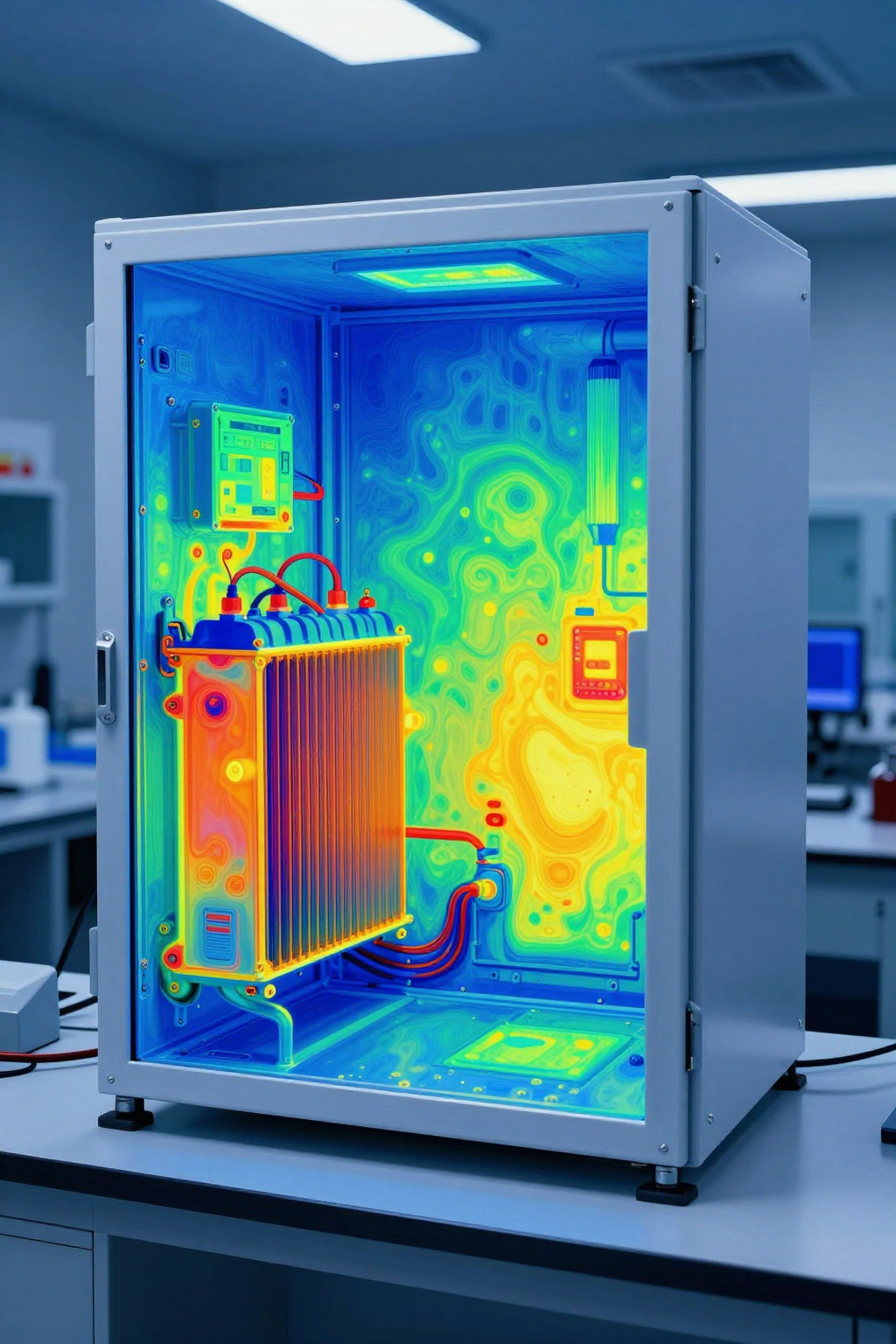
Phase 3: Thermal Performance (The Load Test)
- Simulate Heat Load: Place resistive heaters inside the cabinet matching your estimated load (e.g., 300W). Do not use the actual expensive electronics for the first test.
- Steady State Check: Run the system for 2 hours. Monitor the internal temperature. It should stabilize at the setpoint (e.g., 25°C or 30°C).
- Recovery Test: Turn off the aircon, let the internal temp rise to 45°C, then turn it back on. Measure the time to pull down to 30°C. This confirms pull-down capacity.
Phase 4: Condensate Management
- Humidity Stress: If possible, place a humidifier in the room or a cup of hot water in the cabinet (carefully) to generate moisture.
- Drain Verification: Confirm water flows freely out of the drain tube. Check that the tube is not kinked. If the unit has an internal evaporation system, verify it can keep up with the generation rate.
Expert Field FAQ
Q: How do I determine the correct cooling capacity for my test?
A: You need to sum the active heat load (watts dissipated by electronics) and the passive heat load (solar gain + heat transfer through walls). A common mistake is ignoring solar load, which can account for 30% of the total requirement.
Q: Can I run the Micro DC Aircon directly off a solar panel?
A: Generally, no. You need a battery buffer. Solar output fluctuates wildly with cloud cover. The compressor needs a stable voltage source. Connect the aircon to the battery bank, not the panels directly.
Q: What is the ideal hysteresis setting?
A: A hysteresis of 2°C to 4°C is typical. If set too low (e.g., 0.5°C), the compressor will cycle on/off too frequently. If set too high, internal components may experience thermal stress.
Q: Does the orientation of the unit matter?
A: Yes. Compressor-based units must usually be mounted upright (within ~30 degrees of vertical) to ensure proper oil lubrication in the compressor. Check the specific model’s installation guide.
Q: How often does the unit need maintenance?
A: Unlike filter fans, the internal loop is maintenance-free. The external side (condenser) may need compressed air cleaning if deployed in extremely dusty environments, but there are no filters to replace.
Q: What happens if the battery voltage gets too low?
A: The driver board has built-in low voltage protection. It will cut off the compressor to save the battery (and the compressor) and automatically restart when voltage recovers. Test this threshold during your validation.
Conclusion: Confidence Through Validation
The difference between a reliable field deployment and a maintenance nightmare often comes down to the rigor of the micro dc air conditioner validation test. By systematically verifying sealing, power stability, and thermal capacity under simulated load, you remove the guesswork from the equation.
Remember that a Micro DC Aircon is a system component, not a standalone magic box. Its performance is inextricably linked to the quality of the enclosure sealing, the robustness of the power supply, and the airflow management inside the cabinet. Treat the entire cabinet as the “product,” and validate it as a whole.
Request Sizing & Integration Support
If you are in the design phase and need to confirm which Micro DC Aircon series fits your thermal profile, our engineering team can assist with sizing calculations. Please prepare the following inputs for a productive consultation:
- Target Internal Temperature: (e.g., Max 35°C)
- Max Ambient Temperature: (e.g., 50°C desert condition)
- Heat Load Estimate: (Total Watts of internal electronics)
- Power Source: (Voltage, Battery Chemistry, Current Limits)
- Enclosure Dimensions & Material: (For passive heat transfer calculation)


0 条评论