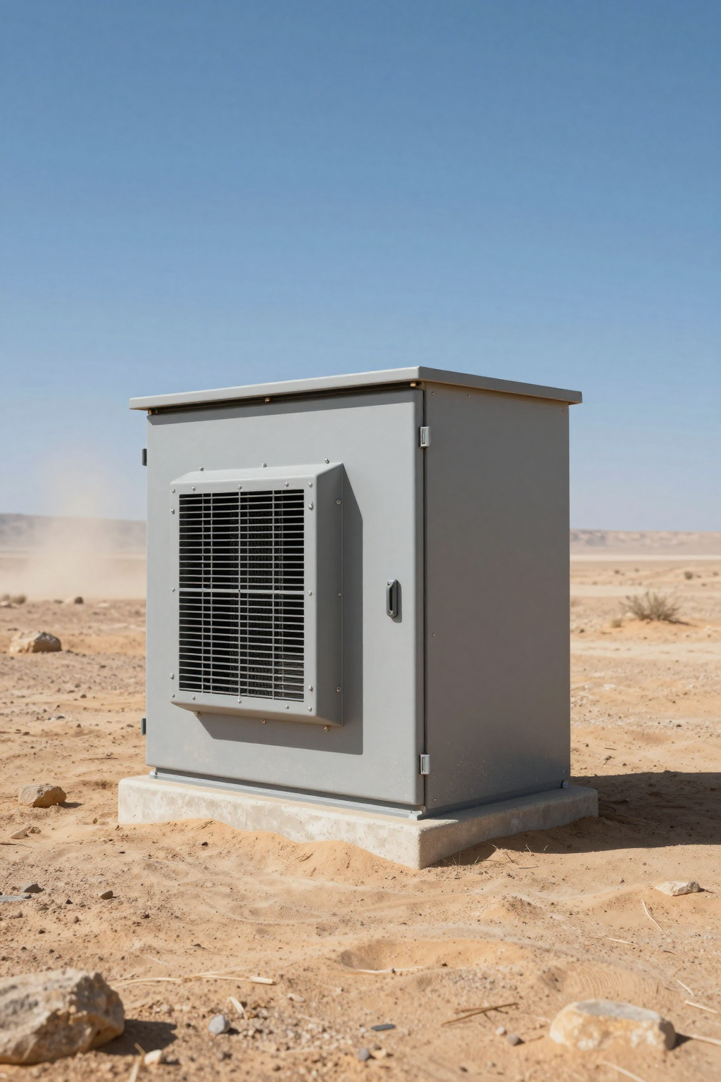
In the controlled environment of a testing laboratory, cooling capacity is a static number. A datasheet might promise 450W of cooling at 35°C ambient, and under strict ISO test conditions, it delivers exactly that. However, for OEM engineers designing systems for outdoor, mobile, or remote deployments, that static number is a dangerous starting point. Once a system leaves the factory, it faces the compounding realities of cooling derating high ambient dust accumulation, and fluctuating power quality.
The gap between “rated capacity” and “installed capacity” is where thermal shutdowns occur. For system integrators, the challenge isn’t just selecting a cooling unit; it is calculating the inevitable performance penalty—the derating—that occurs when a cabinet sits in direct sunlight, filters clog with particulate matter, and battery voltage sags under load. This article provides a consultant-style breakdown of how to quantify these losses and size active cooling systems, such as Micro DC Aircon series, for worst-case survival rather than best-case scenarios.
The Physics of Derating: Why Datasheets Lie (by Omission)
Most cooling components, whether thermoelectric coolers (TECs) or vapor-compression systems, are rated at standard test conditions (often L35/L35, meaning 35°C internal and 35°C external). While useful for baseline comparisons, these metrics rarely reflect the thermal reality of an off-grid telecom cabinet in Nevada or a mining sensor in Western Australia.
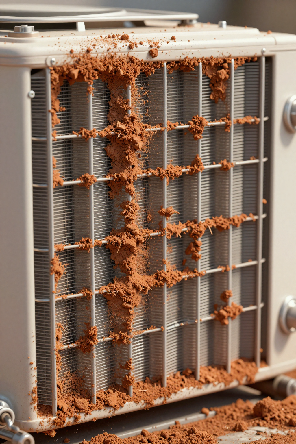
Derating is not a malfunction; it is a physical response to environmental constraints. As ambient temperatures rise, the temperature difference ($\Delta T$) available for heat rejection at the condenser shrinks. To maintain the same cooling effect, the system must work harder, consuming more power while simultaneously losing efficiency. When you add an insulating layer of dust to the heat exchanger or restrict airflow, the system’s ability to reject heat plummets further.
For engineers, the goal is to determine a “Real-World Derating Factor.” If a 500W unit loses 20% capacity at 50°C and another 15% due to filter loading, the usable capacity is only 325W. Ignoring these factors leads to undersized systems that run at 100% duty cycle until they fail.
Deployment Context: Two Scenarios of Thermal Decay
To illustrate how these variables interact, consider two common deployment profiles where standard specs often fail.
Scenario A: The Desert Telecom Node
Context: A 48V DC battery-backed enclosure housing 5G radio equipment.
Constraints: Ambient air temperature reaches 48°C, but solar loading on the cabinet skin pushes the effective surface temperature to 65°C.
The Derating Trap: The engineer selects a cooler based on the 48°C ambient air. However, the “micro-climate” immediately surrounding the condenser intake is significantly hotter due to radiant heat from the cabinet itself and ground reflection. The high ambient temperature increases the pressure head on the compressor, reducing the mass flow rate of the refrigerant. Simultaneously, the battery voltage may dip during discharge cycles, potentially limiting the inverter’s ability to drive the compressor at peak RPM.
Scenario B: The Agricultural Automation Controller
Context: A 24V system mounted on an autonomous harvester.
Constraints: High vibration, intermittent power supply, and extreme dust/chaff levels.
The Derating Trap: The primary enemy here is airflow restriction. Agricultural dust is often fibrous and sticky. Within weeks, a standard filter can lose 50% of its permeability. This chokes the condenser fan, reducing the air volume available to carry heat away. The cooling unit doesn’t stop running, but its capacity drops linearly with airflow reduction, eventually leading to a high-pressure trip or thermal runaway of the internal electronics.
Decision Matrix: Technology vs. Environmental Load
Different cooling architectures respond to environmental stress differently. The table below compares how common solutions handle the primary derating factors.
| Technology | Sub-Ambient Capability | High Ambient Derating Risk | Dust/Clogging Sensitivity | Power Efficiency Trend | Best-Fit Scenario |
|---|---|---|---|---|---|
| Filter Fans (Open Loop) | None (Always > Ambient) | Critical (Fails if Ambient > Target) | High (Direct ingress risk) | Linear (Low power, but zero cooling if clogged) | Clean, indoor, low heat load |
| Thermoelectric (TEC/Peltier) | Yes (Limited Delta T) | High (Efficiency drops sharply as Delta T widens) | Medium (External heatsink fouling) | Poor (COP < 1.0, worsens with heat) | Low heat load (<100W), precise control |
| Micro DC Aircon (Compressor) | Yes (High Delta T) | Moderate (Retains capacity better than TEC) | Medium (Condenser airflow is critical) | High (COP > 2.0, inverter adjusts to load) | High heat load (100W–900W), harsh outdoor |
| Micro Liquid Chiller | Yes (High density) | Low (Remote heat rejection possible) | Low (Sealed loop, radiator can be oversized) | High (Excellent thermal transfer) | Laser, medical, concentrated heat spots |
Implication: For harsh outdoor environments requiring sub-ambient cooling (keeping internals cooler than outside), open-loop fans are physically impossible. TECs struggle with efficiency above 100W loads. Vapor-compression systems (Micro DC Aircon) offer the most resilient balance, provided the condenser is managed correctly.
Quick Selection Rules for the Design Review
- If the ambient temperature exceeds the target internal temperature, then you must use active cooling (Compressor or TEC); fans will only heat the enclosure.
- If dust maintenance is infrequent ( > 6 months), then you must oversize the cooling capacity by at least 30% to account for airflow reduction over time.
- If the power source is battery/solar, then a DC inverter compressor is preferable to a TEC due to the significantly higher Coefficient of Performance (COP).
- If the deployment is in a high-salt or corrosive zone, then standard aluminum fins will degrade; specify coated coils or accept a shorter lifecycle.
- If you need cooling derating high ambient dust protection, then avoid placing the intake near the ground where ground-reflected heat and dust density are highest.
Failure Modes: The Unseen Enemies of Uptime
When a cooling system “fails” in the field, it is rarely a catastrophic component fracture. It is usually a gradual degradation of performance until the threshold is crossed. Understanding these mechanisms is key to prevention.
1. The Insulating Blanket (Condenser Fouling)
Dust does not just block air; it insulates. A layer of dust on the condenser coils acts as a thermal barrier. The refrigerant inside the coil cannot release its heat to the passing air effectively. This causes the condensing temperature to rise. In a vapor-compression cycle, higher condensing pressure forces the compressor to draw more current to do the same amount of work. Eventually, the system hits its high-pressure safety limit and shuts down—often right when cooling is needed most.
2. The Voltage Starvation
In DC-powered applications, cable length and gauge matter. If the wiring is undersized, the inrush current or high-load current of the cooling unit causes a voltage drop. A 24V system might see 21V at the compressor terminals. Many modern BLDC drivers have low-voltage protection. If the voltage sags too low, the compressor may fail to start or limit its speed (RPM), effectively derating its own capacity to stay alive. This “soft failure” results in the enclosure temperature creeping up slowly.
3. Short-Cycling Airflow
If the cool air discharge is blocked by internal components or cable bundles, the cold air bounces back into the return intake. The sensor reads “Target Temperature Reached” and cycles the compressor off. Minutes later, it turns back on. This rapid cycling wears out the drive electronics and fails to cool the actual hot spots in the cabinet.
Engineering Fundamentals: Thermodynamics of Derating
To defend your selection, you must understand the underlying physics. Cooling is essentially moving heat energy from one place to another. The rate at which this happens depends heavily on the temperature difference ($\Delta T$) between the refrigerant and the ambient air.
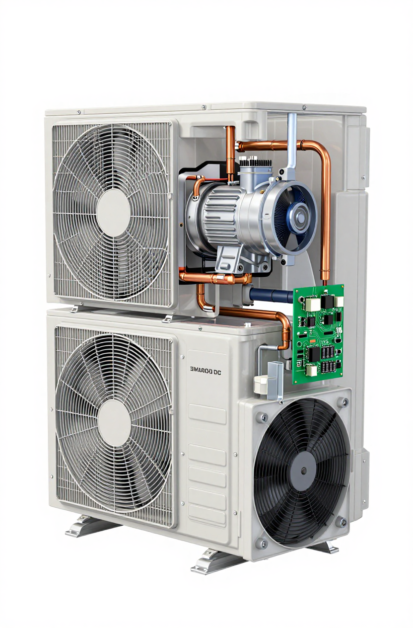
In a standard Micro DC Aircon, the compressor pumps heat from the evaporator (inside) to the condenser (outside). As the outside temperature rises, the “thermal hill” the compressor must climb becomes steeper. The refrigerant must be compressed to a higher pressure to ensure it is hotter than the outside air (so heat can flow out). This increased pressure ratio reduces the volumetric efficiency of the compressor.
Simultaneously, the density of the air decreases slightly as it gets hotter, meaning the fans are moving less air mass for the same RPM. When you combine reduced compressor mass flow with reduced air mass flow, the total cooling capacity drops. This is why a unit rated for 450W at 35°C might only deliver 350W at 55°C. This curve is predictable, but only if you ask for the data.
Performance Data & Verified Specs
When selecting a unit, look for the nominal capacity but apply your safety margins. The following table outlines the verified specifications for the Arctic-tek Micro DC Aircon series. Note that these are nominal ratings; field performance will vary based on the derating factors discussed.
| Model (Pro Series) | Voltage | Nominal Cooling Capacity | Refrigerant | Compressor Type |
|---|---|---|---|---|
| DV1910E-AC | 12V DC | 450W | R134a | BLDC Inverter Rotary |
| DV1920E-AC | 24V DC | 450W | R134a | BLDC Inverter Rotary |
| DV1930E-AC | 48V DC | 450W | R134a | BLDC Inverter Rotary |
| DV3220E-AC | 24V DC | 550W | R134a | BLDC Inverter Rotary |
These units utilize miniature DC compressors (like the QX1901VDL or QX3202VDL) which feature variable speed control. This allows the system to ramp up RPM to combat high heat loads, partially mitigating derating, provided the power supply can support the current draw.
Field Implementation Checklist
To minimize the impact of cooling derating high ambient dust, follow this integration checklist:
Mechanical & Thermal
- Solar Shielding: Always install a sunshade or double-wall the enclosure. Direct solar load can add 200W–300W of heat that the cooler must remove before it even touches the component heat load.
- Airflow Management: Ensure the external condenser intake and exhaust are not obstructed. Maintain at least 100mm of clearance.
- Sealing: Verify the enclosure meets the target IP/NEMA rating. Leaks introduce humidity, which forces the cooler to waste energy on latent cooling (removing water) rather than sensible cooling (lowering temperature).
Electrical
- Cable Sizing: Calculate voltage drop for the maximum current (not average). Use thicker gauge wire if the run is long to prevent low-voltage cutouts.
- Soft Start: Confirm the DC compressor driver handles inrush current gracefully to avoid tripping battery protection circuits.
Maintenance
- Filter Schedule: Define a cleaning interval based on the environment. In mining or agriculture, this might be weekly. In urban telecom, perhaps semi-annually.
- Coil Inspection: Check for salt corrosion or mud caking annually.
Expert Field FAQ
Q: How much safety margin should I add for high ambient conditions?
A: A common rule of thumb is to derate the cooling capacity by 1.5% to 2% for every degree Celsius above the rated temperature (usually 35°C). If you expect 55°C, that is a 20°C delta, implying a potential 30–40% capacity reduction. Always size up.
Q: Can I just use a bigger fan to fight the dust?
A: Not necessarily. Higher static pressure fans can help push through clogged filters, but they also consume more power and create more noise. The better solution is often a larger filter surface area to reduce face velocity and delay clogging.
Q: Does the refrigerant type affect derating?
A: Yes. R134a is standard, but R290 (Propane) often has better thermal conductivity and efficiency in high ambient conditions. However, R290 has flammability constraints that must be managed.
Q: What happens if the battery voltage drops to 22V on a 24V system?
A: The Micro DC Aircon driver board will typically continue to operate, but it may limit the maximum compressor RPM to prevent further voltage sag. This means you lose peak cooling capacity exactly when the battery is likely struggling (e.g., end of a long, hot discharge cycle).
Q: How do I calculate cooling derating high ambient dust safety margins?
A: Start with your worst-case heat load. Add the solar load. Then, assume the cooler will only deliver ~70% of its datasheet nominal capacity due to the combined effects of heat and dirt. If the math still works, your design is robust.
Q: Is a closed-loop system always better than open-loop?
A: For reliability, yes. Closed-loop (Aircon or Air-to-Air Heat Exchanger) isolates the sensitive electronics from the dirty outside air. Open-loop fans bring dust and humidity directly onto the circuit boards, which is the primary cause of corrosion and short circuits.
Conclusion: Designing for the Worst Day
The success of an outdoor deployment is not determined by how the system performs on an average day, but how it survives the hottest, dustiest day of the year. Derating is an unavoidable law of physics, but it is manageable with correct sizing and integration.
By acknowledging the realities of cooling derating high ambient dust accumulation and power constraints, engineers can move beyond datasheet optimism. Selecting a robust solution like the Micro DC Aircon series, oversizing for thermal decay, and protecting the intake path are the hallmarks of a resilient design. Do not just buy a cooling unit; buy a safety margin.
Request a Sizing Consultation
Stop guessing at safety margins. To get a precise sizing recommendation for your specific deployment, send our engineering team the following inputs:
- Ambient Max & Solar Load: (e.g., 50°C + direct sun)
- Target Internal Temp: (e.g., maintain < 40°C)
- Heat Load Estimate: (Total component dissipation in Watts)
- Power Source: (Voltage, Battery Chemistry, Current Limits)
- Sealing Target: (IP55, IP65, NEMA 4X)
- Service Interval: (How often can a technician visit?)


0 条评论