Angle: The critical decision moment for an engineer is selecting the correct power delivery strategy for a compact DC air conditioner to prevent field failures. Two common failure modes are system-wide brownouts caused by compressor inrush current and sensor data corruption from electromagnetic interference (EMI). The dominant constraint in these scenarios is almost always the integrity of the shared DC power bus in a complex industrial machine.
Your Guide to 12v 24v dc air conditioner integration industrial; emi dc compressor Management
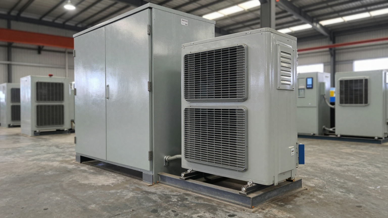
Integrating a compact DC air conditioner into an industrial enclosure seems straightforward—until it isn’t. An OEM engineer designs a cooling solution to solve a thermal problem, only to inadvertently create a new, more insidious electrical one. The primary thermal challenge is solved, but now the equipment experiences intermittent reboots, sensor drift, or communication errors that defy easy diagnosis. The stakes are high: production halts, damaged electronics, and a compromised reputation for reliability. These issues often trace back to the electrical integration of the cooling unit, not the unit itself.
By the end of this technical guide, you will be equipped to design and validate a robust power delivery architecture for any compact DC cooling system. You will be able to anticipate and mitigate the most common electrical failure modes before they happen. In this article, we prioritize electrical stability and EMI mitigation over raw cooling power, because a system that is electrically unstable is fundamentally more compromised than one that is merely running warm. A successful 12v 24v dc air conditioner integration industrial; emi dc compressor strategy is about system-level reliability.
Deployment Context: Where Electrical Integration Fails
Theoretical knowledge is useful, but seeing where integrations fail in the real world provides the most valuable lessons. Here are two common scenarios where improper electrical design led to significant operational problems.
Scenario A: Autonomous Mobile Robot (AMR)
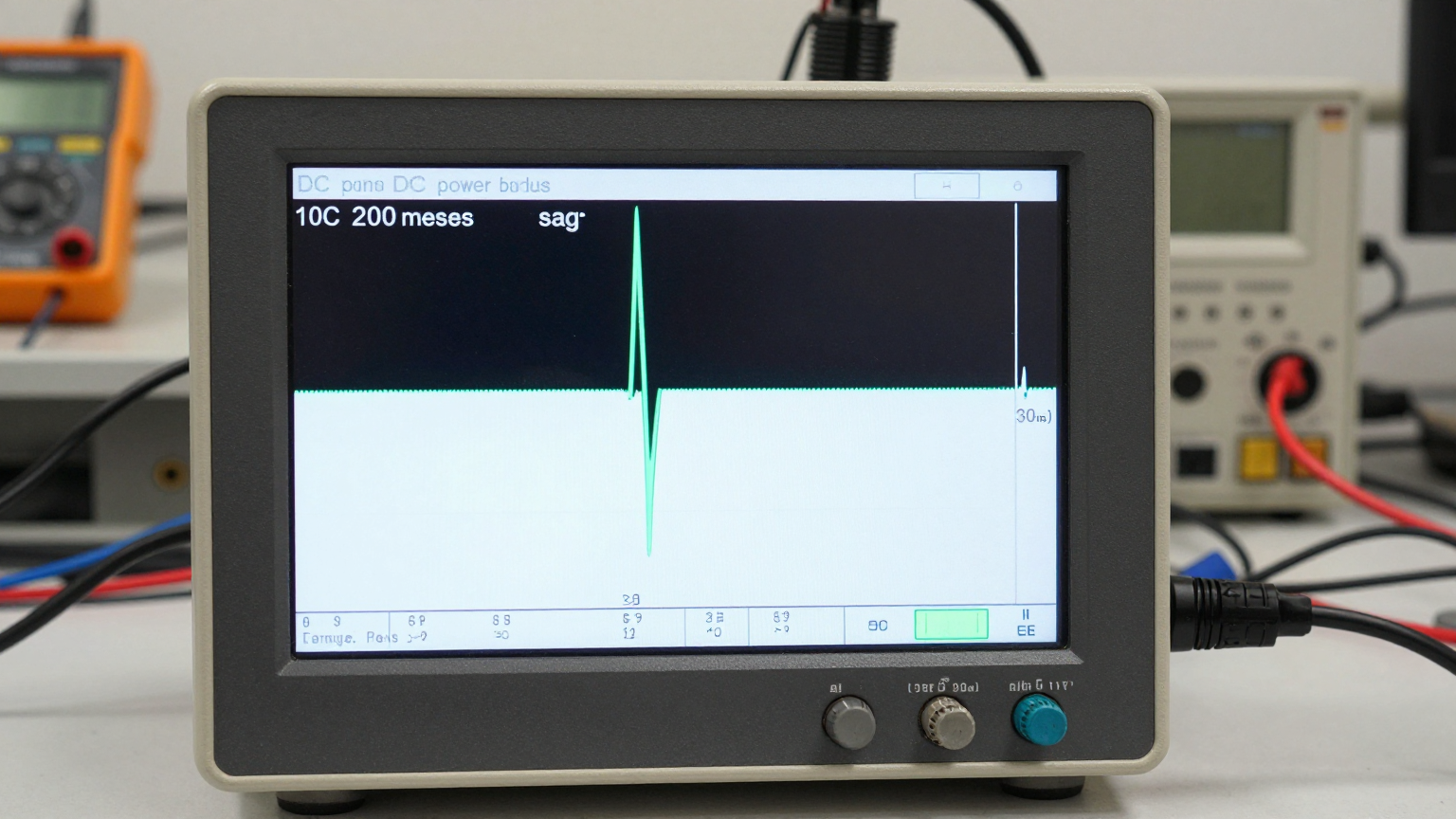
An AMR operating in a warehouse relies on a central 24V lithium-ion battery pack to power its drive motors, navigation computer, LiDAR sensors, and a small DC air conditioner cooling the primary processing unit. The engineering team connected the air conditioner to the main power distribution bus. During operation, the AMR would randomly freeze and require a hard reboot. The cause was traced to the DC compressor startup: its high inrush current created a momentary voltage sag on the bus, dropping the voltage just below the navigation computer’s minimum threshold and causing a brownout reset. The thermal problem was solved, but the robot’s core function was compromised.
Scenario B: Remote Telecom Enclosure
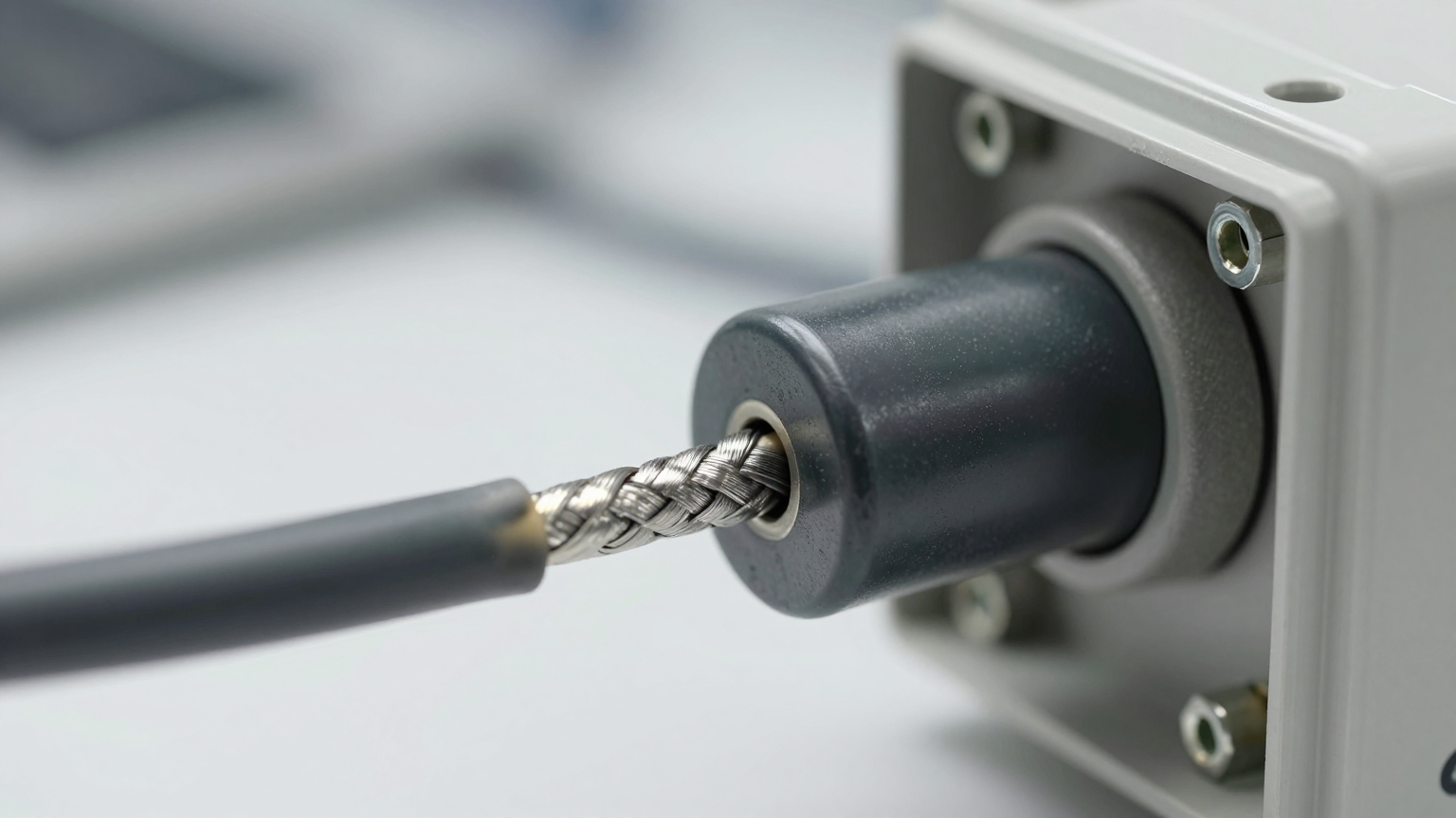
A sealed telecom cabinet in a desert environment, powered by a solar and battery array, used a 12V DC air conditioner to protect sensitive radio frequency (RF) amplifiers. The system experienced persistent, low-level data corruption on its primary uplink. After weeks of troubleshooting software and RF components, the issue was identified as radiated electromagnetic interference. The unshielded power cable to the air conditioner, running parallel to sensitive signal lines, was acting as an antenna, broadcasting noise generated by the emi dc compressor driver electronics. This noise was enough to degrade the signal-to-noise ratio of the RF amplifiers, impacting service quality.
Common Failure Modes & System Constraints
When planning a 12v 24v dc air conditioner integration industrial; emi dc compressor project, engineers must anticipate potential failure points beyond simple thermal performance. These issues are often electrical and mechanical in nature, and they are far easier to design out than to fix in the field. Here are the most common failure modes, ranked by their likelihood and impact.
- Intermittent System Resets → Caused by voltage drop from compressor inrush current → Why it matters: Corrupts data, causes unpredictable machine states, and is extremely difficult to diagnose as it leaves no clear fault code.
- Sensor Noise or Signal Drift → Caused by radiated EMI from unshielded DC power lines → Why it matters: Leads to incorrect control decisions, false alarms, and a general loss of trust in the system’s instrumentation.
- Nuisance Fuse Tripping → Caused by using a fast-blow fuse instead of a recommended time-delay (slow-blow) type → Why it matters: Results in unnecessary downtime and service calls, eroding customer confidence.
- Gradual Cooling Performance Degradation → Caused by high-resistance connections from improper wire crimps or corrosion → Why it matters: Overheats wiring, creating a fire risk, while simultaneously starving the unit of power and reducing its service life.
- Premature Compressor Failure → Caused by an unstable input voltage or excessive ripple from a low-quality power supply → Why it matters: Stresses the compressor motor and control electronics, leading to costly, premature replacement.
- Control Board Malfunctions → Caused by conducted EMI being fed back onto the main power bus → Why it matters: Can affect any other sensitive electronic module sharing the same power source, creating system-wide ghost failures.
- Inability to Start Under Load → Caused by cumulative voltage drop from undersized wiring over a long distance → Why it matters: The system works on the bench but fails in the final installation, requiring expensive and time-consuming rewiring.
Engineering Fundamentals: The DC Compressor as a Dynamic Load
The core of any successful 12v 24v dc air conditioner integration industrial; emi dc compressor project is understanding that the air conditioner is not a simple resistive load. It is a dynamic electromechanical system. The miniature DC compressor motor requires a large amount of current for a very short duration to overcome inertia and initial pressure—this is the inrush current. After starting, the current draw drops to a much lower, stable level known as the steady-state current.
This dynamic behavior is the source of most integration problems. A common misconception illustrates this perfectly:
- Misconception: “My 24V power supply is rated for 10 amps, and the air conditioner’s spec sheet says it draws 6 amps steady-state. I have plenty of headroom.”
- Correction: The power supply’s ability to handle the peak inrush current is what truly matters. That 6-amp unit might draw 15 amps or more for 100-200 milliseconds during startup. If the 10-amp power supply cannot deliver this peak current without its output voltage collapsing, it will trigger the air conditioner’s own undervoltage lockout protection, or worse, it will cause a brownout that affects other devices on the same power rail. A power supply must be specified based on peak load, not average load.
Similarly, the switching electronics that drive the brushless DC compressor motor are a source of high-frequency electrical noise. Without proper filtering, shielding, and grounding, this EMI can be conducted back onto the power lines or radiated into adjacent components. Treating the air conditioner as a sensitive, noise-generating device from the start is essential for reliable integration.
Specification Gateway: Go/No-Go Electrical Parameters
Before selecting a compact DC air conditioner, you must obtain a clear and comprehensive electrical specification sheet from the manufacturer. If these details are not readily available, you cannot perform a reliable integration analysis. Do not proceed without confirming the following go/no-go parameters, as they are foundational to a successful 12v 24v dc air conditioner integration industrial; emi dc compressor design.
- Peak/Inrush Current and Duration: This is the single most critical value for sizing your power supply or evaluating the load on a shared bus. It’s a non-negotiable parameter.
- Operating Voltage Range: This defines the absolute upper and lower voltage limits. Pay close attention to the undervoltage lockout (UVLO) threshold, as your delivered voltage under peak load must remain above this level. This value varies by model.
- Recommended Fuse Type and Rating: The manufacturer must specify whether a time-delay (slow-blow) or other specific fuse class is required to handle the inrush current without nuisance trips. This is a critical safety and reliability component.
- EMI Compliance Information: While full compliance data may vary, look for any mention of internal filtering or adherence to standards (e.g., CISPR, FCC). This gives a baseline for how much external mitigation you may need to add.
- Recommended Wire Gauge vs. Distance Chart: A reliable supplier will provide guidance on the minimum wire gauge needed to keep voltage drop within acceptable limits over various cable lengths. This depends on configuration.
- Control Signal Logic Levels and Type: If you plan to control the unit with a PLC or microcontroller, you must know the required voltage levels (e.g., 5V TTL, 24V logic) and signal type (e.g., PWM, analog voltage) for functions like variable speed control.
- Standby Power Consumption: For battery-powered or energy-sensitive applications, the power consumed when the compressor is off can be a significant factor in the overall energy budget.
Engineering Selection Matrix: Electrical Integration Logic Gates
A lead engineer must guide the integration process through a series of logic gates. These gates force a decision on critical design trade-offs, ensuring that electrical stability is not sacrificed for thermal performance. Proper 12v 24v dc air conditioner integration industrial; emi dc compressor requires this level of scrutiny.
Logic Gate 1: Power Source Architecture
- The Constraint Gate: Shared DC Power Bus vs. Dedicated Power Supply.
- The Decision Trigger: If the main DC bus powers any component that cannot tolerate a voltage sag of more than 5% (e.g., microcontrollers, precision analog sensors, communication hardware).
- Engineering Resolution: The air conditioner must be electrically isolated. This is achieved by either providing a completely dedicated power supply for the cooling unit or by designing a heavily filtered power branch with significant local capacitance to service the inrush current without affecting the main bus.
- Integration Trade-off: This increases the bill of materials cost and physical footprint within the enclosure but is the most effective way to guarantee total system reliability by decoupling the noisy, high-current cooling load.
Logic Gate 2: EMI Mitigation Strategy
- The Constraint Gate: Proximity to EMI-Susceptible Components.
- The Decision Trigger: If the air conditioner unit or its power cabling will be located within 30-40 cm of unshielded analog sensor leads, RF antennas/receivers, or high-speed data lines (e.g., Ethernet, CAN bus).
- Engineering Resolution: Mandate the use of shielded power cables for the air conditioner. The cable shield must be properly terminated to a low-impedance chassis ground point, typically only at the power source end, to avoid ground loops. Additionally, place large ferrite beads on the power lines as close to the air conditioner’s power input as possible to suppress high-frequency noise from the emi dc compressor.
- Integration Trade-off: This increases cable cost and assembly complexity. However, it is a low-cost insurance policy against intermittent, hard-to-diagnose field failures caused by EMI.

Logic Gate 3: Voltage Drop and Wiring Specification
- The Constraint Gate: Cable Run Length vs. Conductor Wire Gauge.
- The Decision Trigger: If the physical distance between the power supply terminals and the air conditioner’s power input terminals exceeds 1 meter.
- Engineering Resolution: Perform a voltage drop calculation based on the peak inrush current, not the steady-state current. The goal is to keep the voltage drop below 3% of the nominal bus voltage. This almost always results in selecting a wire gauge one or two sizes larger than what would be considered adequate for the steady-state current alone.
- Integration Trade-off: This requires using heavier, more expensive, and less flexible wiring, which can complicate cable routing in a dense enclosure. Failing to do this is a leading cause of units that fail to start reliably in the final application. This is a fundamental step in any serious 12v 24v dc air conditioner integration industrial; emi dc compressor plan.
Implementation & Verification Checklist
A robust design must be followed by a meticulous implementation and verification process. Use this checklist to ensure the design is translated into a reliable final assembly.
-
Mechanical Installation
- Mounting: Ensure the unit is securely fastened. Use supplied vibration-dampening mounts if provided to prevent transferring mechanical noise to the enclosure.
- Sealing: Verify that any mounting gaskets are properly compressed to maintain the enclosure’s NEMA or IP rating. Check for any gaps or unsealed penetrations.
- Airflow Integrity: Confirm that both the internal (evaporator) and external (condenser) fans have unobstructed airflow paths. Blocked airflow is a common cause of poor performance.
-
Electrical Wiring & Protection
- Power Source Verification: Double-check that the power supply’s peak current rating exceeds the air conditioner’s specified inrush current.
- Wiring Practices: Use the specified wire gauge. For unshielded cables, twist the positive and negative power leads together to reduce the loop area and minimize EMI radiation. Ensure all crimps are made with the correct tool for a low-resistance connection.
- Fusing: Install the manufacturer-specified fuse (type and rating) as close to the power source as possible on the positive supply line.
- Grounding: Connect the unit’s chassis ground lug and the power cable shield (if used) to a single, low-impedance star ground point to prevent noise currents from circulating.
-
Thermal & Electrical Validation
- Sensor Placement: Position the thermal control sensor in a location that accurately reflects the temperature of the critical components being protected. Avoid placing it in the direct, cold airflow from the unit.
- Acceptance Test: This is the most critical step. Under full system load, use a multimeter or oscilloscope to measure the voltage directly at the air conditioner’s power input terminals during compressor startup. The measured voltage must remain safely above the unit’s undervoltage lockout threshold.
-
Maintenance & Serviceability
- Access: Ensure that service technicians can access condenser coils and fans for periodic cleaning, as dust and debris accumulation will degrade performance.
- Inspection Triggers: Define inspection points in the service manual, specifically checking for the tightness of high-current electrical connections.
Frequently Asked Questions (FAQ)
Here are answers to common objections and questions that arise during the integration process.
Should I choose a 12V or 24V system?
For the same cooling capacity, a 24V system is almost always preferable in an industrial context. It draws half the current of a 12V system, which significantly reduces voltage drop over the same length of wire and allows for the use of smaller, lighter, and less expensive cabling. The principles of 12v 24v dc air conditioner integration industrial; emi dc compressor apply to both, but 24V makes the electrical challenges easier to manage.
What if my enclosure must be fully sealed to IP67?
This is an ideal application for a compact DC air conditioner. The unit operates in a closed-loop configuration, removing heat from the internal air and rejecting it to the outside without any air exchange. This maintains the integrity of the seal against dust, water, and other contaminants. Our Micro DC Aircon series is designed for these exact scenarios.
How do I manage condensation?
Condensation (condensate) forms on the cold evaporator coil. All units are designed with a drain port. In mobile applications, this can be routed outside the enclosure. In stationary sealed enclosures, it’s critical to ensure the internal enclosure temperature setpoint is kept above the dew point of the internal air to prevent condensation from forming in the first place.
My equipment is in direct sun. How does that affect power and performance?
Direct solar radiation adds a significant thermal load to the enclosure. This means the compressor will run more frequently and for longer durations, increasing the total average power consumption. You must account for this additional heat load in your thermal calculations to ensure the unit is not undersized.
What is the single most important thing to measure before starting the integration?
The voltage stability of your DC power source. You must know its actual output voltage under no-load and full-load conditions and understand its transient response. Measure the voltage at the intended connection point to account for any existing voltage drop in your system.
How can I validate the EMI performance after installation?
A simple but effective method is to monitor the noise floor of a sensitive analog sensor or check the error rate of a communication bus (like CAN or Ethernet) with the air conditioner off, and then again with it running. A significant increase in noise or errors points to an EMI problem that needs to be addressed with improved shielding, grounding, or filtering. This is a key validation step for the emi dc compressor.
Why is an emi dc compressor a concern in industrial settings?
Industrial environments are electrically noisy, but they are also filled with highly sensitive components like PLCs, VFDs, sensors, and robotic controllers. The noise from a poorly integrated DC compressor can be the tipping point that causes difficult-to-diagnose intermittent faults in these adjacent systems, leading to costly downtime. This is why a proper 12v 24v dc air conditioner integration industrial; emi dc compressor strategy is so important, especially for applications like telecom components cooling.
Conclusion: Best-Fit Integration Strategy
A successful 12v 24v dc air conditioner integration industrial; emi dc compressor project is defined by electrical robustness, not just thermal performance. The approach detailed here—prioritizing power source stability, mitigating EMI at the source, and managing voltage drop proactively—is essential for mission-critical applications where reliability is non-negotiable. This includes medical devices, autonomous robotics, remote telecommunications, and any industrial automation system where downtime is unacceptable.
For simpler applications with isolated power sources and low sensitivity to electrical noise, some of these steps may be relaxed. However, treating every integration with this level of engineering discipline is the surest path to a reliable product that performs flawlessly in the field. If you are navigating the complexities of a compact cooling project, our engineering team can help analyze your power budget, enclosure geometry, and environmental constraints to specify a correctly sized and configured solution.


0 条评论