Angle Lock: The decision is choosing between passive/vented cooling and a closed-loop active system. The primary failure modes are thermal shutdown from solar load and contaminant ingress from compromised seals. The dominant constraint is maintaining a certified NEMA/IP seal while actively removing heat in high-ambient conditions.
A Practical Guide to Outdoor Sealed Enclosure Cooling
An industrial variable frequency drive (VFD) inside a steel control panel fails on the hottest day of the year, shutting down a critical remote pumping station. The cost of the VFD is trivial compared to the cost of the emergency dispatch and operational downtime. The cause wasn’t a faulty component, but a thermal management strategy that failed to account for the physics of a sealed box under direct sun. This scenario is a common and expensive reality for system integrators deploying sensitive electronics outdoors. Vented enclosures invite failure from dust, moisture, and corrosion, while sealed enclosures trap heat, creating a micro-environment that accelerates component aging and causes unpredictable faults. The central challenge of outdoor sealed enclosure cooling is removing heat without compromising the integrity of the seal.
By the end of this article, you will be able to determine the precise point at which passive methods become insufficient and a compact, active refrigeration system becomes the only viable engineering choice. In this analysis, we prioritize closed-loop, active cooling to maintain seal integrity over passive or vented solutions that are fundamentally unsuited for harsh, high-reliability deployments.
Deployment Context: Kiosks, Panels, and Sensors
The thermal challenges of outdoor electronics vary significantly by application. The heat source, enclosure material, and environmental hazards dictate the cooling strategy. Two common scenarios illustrate the stakes.
Scenario A: Digital Signage Kiosk
A public transit authority deploys interactive kiosks with high-brightness displays and embedded PCs. The initial design used filtered fans for cooling. Within six months, units began failing. An inspection revealed that fine, conductive brake dust from passing trains had bypassed the filters, shorting out motherboards. Furthermore, high humidity led to condensation on internal components during rapid temperature drops overnight. The constraint was not just heat, but the combination of a high, variable thermal load from the display backlight and the presence of airborne metallic and humid contaminants.
Scenario B: Remote Telemetry Control Panel
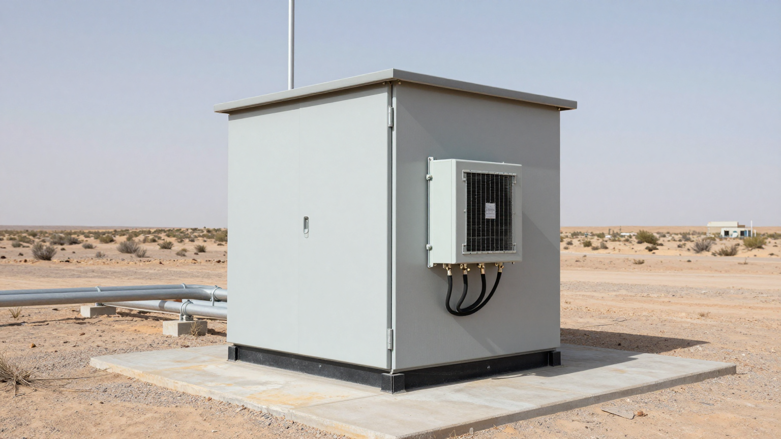
A pipeline monitoring station in an arid, desert environment uses a NEMA 4X sealed enclosure to protect PLCs, communication hardware, and backup batteries. There is no grid power; the system runs on a solar and battery array. On summer afternoons, direct solar radiation on the enclosure’s surface, combined with the internal heat from the electronics, pushed the internal temperature above 70°C. This exceeded the 60°C operating limit of the PLC, causing intermittent data transmission failures. The dominant constraint was the extreme solar load and high ambient temperature, which made any passive cooling solution that relies on a favorable ambient-to-internal temperature difference completely ineffective.
Common Failure Modes and System Constraints
When designing for outdoor sealed enclosure cooling, engineers must anticipate a specific set of cascading failures. Understanding these symptoms and their root causes is the first step in designing a resilient system.
- Symptom: Intermittent system resets or data errors → Cause: CPU or PLC clock cycle timing drifts as it exceeds its maximum operating temperature → Why it matters: Leads to unpredictable behavior and data corruption that is difficult to diagnose remotely.
- Symptom: Premature power supply failure → Cause: Electrolytic capacitors dry out at an exponentially faster rate for every 10°C rise in temperature → Why it matters: Results in catastrophic, non-recoverable system failure and requires a physical service call.
- Symptom: Reduced battery lifespan → Cause: Charging or storing batteries in high-temperature environments causes irreversible chemical degradation → Why it matters: Compromises the reliability of backup power systems, a critical failure in off-grid applications.
- Symptom: Clogged heat sinks and fans → Cause: Dust and particulate ingress from improperly sealed or fan-cooled enclosures → Why it matters: A gradual reduction in cooling performance that eventually leads to thermal shutdown.
- Symptom: Corroded connectors and PCB traces → Cause: Condensation forming as the enclosure temperature drops below the dew point of the trapped internal air → Why it matters: Causes short circuits and signal integrity issues that are difficult to trace.
- Symptom: Fogged sensor optics or camera lenses → Cause: High internal humidity condensing on cooler optical surfaces → Why it matters: Renders data from optical sensors or security cameras useless.
- Symptom: Warped enclosure gaskets → Cause: Over-pressurization from air expansion as the enclosure heats up → Why it matters: Compromises the NEMA/IP rating, creating a pathway for future water and dust ingress.
Engineering Fundamentals: The Closed-Loop Imperative
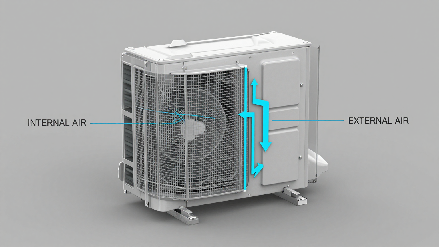
The core principle for successfully cooling a sealed enclosure is the closed-loop system. This approach uses two completely separate air circuits to transport heat from inside the box to the outside world without allowing the two air streams to mix. This is the same principle used in a vehicle’s air conditioning system and is the only way to remove heat while preserving a certified seal.
A compact vapor-compression system, such as a Micro DC Aircon, operationalizes this principle. The internal evaporator coil and fan absorb heat from the air inside the enclosure, cooling the critical components. This heat is transferred via refrigerant to an external condenser coil, where a second fan dissipates it into the ambient environment. The gasket between the unit’s internal and external sections maintains the enclosure’s seal.
Misconception: A powerful fan or a simple heat sink is sufficient for outdoor enclosures.
Correction: This is a critical misunderstanding. A fan can only work if the outside air is both cooler than the desired internal temperature and clean enough to be introduced into the enclosure. In most outdoor scenarios, neither is true. A fan in a sealed box merely circulates hot air, doing nothing to remove the thermal energy. A heat sink relies on convection and radiation, which are often not enough to overcome the combined internal heat load and external solar load. For true outdoor sealed enclosure cooling, you must actively transport heat out of the sealed volume.
Specification Gateway for Active Cooling Units
When you have determined that an active, closed-loop system is necessary, the selection process becomes data-driven. The key is to match the performance of the cooling unit to the thermal load and power constraints of your system. The table below shows example specifications from the Rigid Chill Micro DC Aircon series, which are designed for these compact applications.
| Model (Example) | Input Voltage (VDC) | Nominal Cooling Capacity (W) | Refrigerant |
|---|---|---|---|
| DV1910E-AC (Pro) | 12V | 450W | R134a |
| DV1920E-AC (Pro) | 24V | 450W | R134a |
| DV1930E-AC (Pro) | 48V | 450W | R134a |
| DV3220E-AC (Pro) | 24V | 550W | R134a |
To use these specifications effectively, first calculate your total internal heat load by summing the power consumption of all enclosed components. Next, add any external heat load, such as solar gain. Select a unit with a nominal cooling capacity that exceeds your calculated total load by a safety margin of 20-25%. Finally, match the input voltage to your system’s DC power bus—24V is common for industrial controls, while 48V is standard in telecommunications.
Engineering Selection Matrix: Logic Gates for Integration
A lead engineer must navigate a series of critical decision points to arrive at the correct thermal solution. These logic gates force a clear-eyed assessment of the project’s hard constraints.
Logic Gate 1: The Sealing Mandate
- Constraint Gate: The enclosure requires an IP (Ingress Protection) or NEMA rating to protect against environmental hazards like dust, water, or corrosive agents.
- Decision Trigger: If the deployment environment contains airborne particulates (dust, salt), moisture (rain, humidity, washdowns), or requires a specific certification (e.g., NEMA 4X for corrosion resistance).
- Engineering Resolution: All vented or fan-and-filter solutions are immediately disqualified. The selection is narrowed exclusively to closed-loop systems, such as heat exchangers or active air conditioning units, that can maintain the seal.
- Integration Trade-off: This decision increases the upfront system cost and complexity but eliminates the far greater downstream costs of maintenance, cleaning, and component failure due to contamination.
Logic Gate 2: The Thermal Delta Requirement
- Constraint Gate: The relationship between the maximum allowable internal temperature and the peak external ambient temperature.
- Decision Trigger: If the required internal temperature must be held at or below the peak ambient temperature. For example, if internal components must stay below 40°C when the outside air temperature hits 50°C.
- Engineering Resolution: Passive solutions like heat exchangers, which can only cool to a temperature *above* ambient, are disqualified. The system requires active refrigeration to create a negative thermal delta. A vapor-compression Micro DC Aircon is the direct solution.
- Integration Trade-off: This path requires allocating a larger portion of the power budget to the cooling system. However, it is the only way to guarantee the performance and longevity of electronics that would otherwise have to be derated or would fail outright.
Logic Gate 3: Heat Load Density
- Constraint Gate: The total thermal load (in watts) generated by the internal components versus the physical volume and surface area available for the cooling unit.
- Decision Trigger: If the calculated heat load is high (typically > 150W) and the enclosure is compact, leaving no room for bulky heat sinks or inefficient thermoelectric coolers.
- Engineering Resolution: The solution must have a high cooling power density (watts of cooling per cubic centimeter). Miniature vapor-compression systems are significantly more efficient and power-dense than thermoelectric (Peltier) devices, making them the superior choice for removing substantial heat from a small space.
- Integration Trade-off: While more mechanically complex than a solid-state thermoelectric cooler, a miniature compressor-based system delivers far more cooling performance for a given power input and physical footprint, enabling more powerful electronics to be deployed in smaller enclosures.
Implementation and Verification Checklist
Proper installation is as critical as proper selection. A perfectly specified unit can fail if it’s integrated poorly. Follow this checklist to ensure performance and reliability.
- Mechanical Integration
- Sealing Surface: Ensure the enclosure cutout is clean, burr-free, and perfectly flat. Apply the supplied gasket evenly and torque the mounting hardware to the manufacturer’s specification to create a continuous, watertight seal.
- Airflow Integrity: Verify that the internal and external fans are unobstructed. Ensure that internally mounted components, cables, or brackets do not block the path of the cold air supply or the return air path.
- Condensate Management: If the unit will be cooling the internal air below its dew point, moisture will condense. Ensure any provided drain tube is properly routed to the exterior and is not kinked or blocked.
- Electrical Integration
- Power Budget: Connect the unit to a stable DC power source that can handle both the steady-state current and the initial inrush current on startup. Use a dedicated circuit with appropriate fusing.
- Wiring: Use the recommended wire gauge for the current and distance to prevent voltage drop, which can impair performance. Ensure all connections are secure and protected from vibration.
- Thermal Verification
- Sensor Placement: Place your primary temperature monitoring sensor near the most heat-sensitive component or at the top of the enclosure where hot air collects. Do not place it directly in the path of the cold air from the cooling unit, as this will give a false reading and cause short-cycling.
- Acceptance Testing: After installation, perform a full-load test. Run the internal electronics at maximum capacity on a warm day (or use a heat source in a controlled test) to verify the cooling unit can maintain the target temperature indefinitely.
Frequently Asked Questions (FAQ)
- Should I choose a thermoelectric (Peltier) cooler or a DC air conditioner?
- For very low heat loads (under 100W) where efficiency is not a primary concern, a thermoelectric cooler can be a simpler solid-state option. For heat loads above 100-150W, a vapor-compression DC air conditioner is vastly more energy-efficient (higher COP) and can remove much more heat from a compact enclosure.
- How do I manage condensation inside a sealed enclosure?
- The best strategy is to set the thermostat so the internal temperature remains above the dew point. If you must cool below the dew point, you must actively manage the resulting water. A properly installed cooling unit will have an integrated condensate drain to channel water outside the enclosure.
- What is the impact of direct solar radiation on my cooling needs?
- Direct sun on an enclosure’s surface adds a significant external heat load, which can be several hundred watts depending on the size, color, and material. This must be calculated and added to your internal heat load. Using a solar shield or painting the enclosure a reflective, light color can dramatically reduce this load.
- My enclosure needs a NEMA 4X rating for a corrosive, washdown environment. What are my options?
- Standard cooling units may use materials susceptible to corrosion. For NEMA 4X applications, you must specify a unit with a suitable housing, such as stainless steel, and corrosion-resistant coatings on the external coils. Discuss these customization options with the manufacturer.
- What is the first thing I must measure before selecting a cooler?
- The total internal heat load in watts. This is the most critical variable. Calculate it by summing the maximum power consumption of every component inside the enclosure (VFDs, power supplies, processors, radios, etc.). Be conservative and design for the worst-case scenario.
- How can I validate the cooling system is working correctly after installation?
- Log the internal temperature over a 24-hour cycle under full operational load. The data should show the cooling unit cycling on and off to maintain the temperature within a narrow band around your setpoint, even during the hottest part of the day.
Conclusion: Matching the Tool to the Physics
The engineering of effective outdoor sealed enclosure cooling is a process of elimination. When the operational environment is harsh and system reliability is paramount, solutions that compromise the enclosure’s seal are not a viable option. When the combination of internal and external heat loads makes it impossible to keep components within their safe operating range, active refrigeration becomes a necessity. A compact, efficient Micro DC Aircon is the best-fit solution when a sealed enclosure must be cooled below ambient temperature, and when power density and energy efficiency are key design constraints.
This approach is not for every application. If an enclosure can be vented and the environment is clean, a fan may be sufficient. But for the growing number of rugged, sealed electronic systems deployed in the real world—from remote control panels to public-facing kiosks—a robust, closed-loop cooling strategy is fundamental to the system’s success. Our engineering team can assist with thermal load calculations and help configure a cooling solution tailored to your specific enclosure geometry, power constraints, and environmental challenges.


0 条评论