The Hidden Cost of Hysteresis: Why Control Engineers Are Abandoning Fixed-Speed Cooling
In precision industrial automation and mobile cooling applications, thermal stability is rarely a “set it and forget it” parameter. For control engineers, the standard on/off vapor compression cycle presents a fundamental conflict: the binary nature of a fixed-speed compressor versus the analog reality of environmental heat loads. When a cooling system relies on a simple thermostatic switch, the result is inevitable hysteresis—a sawtooth temperature profile that oscillates around the setpoint rather than maintaining it. In rugged, battery-powered, or precision electronics environments, this oscillation is not just an inefficiency; it is a failure mode.
The shift toward the variable speed dc compressor represents a move from reactive cooling to predictive, proportional thermal management. Unlike traditional AC compressors that run at a fixed RPM (locked to grid frequency) or fixed-speed DC units that simply cycle on and off, a variable speed dc compressor utilizes a Brushless DC (BLDC) inverter to modulate speed dynamically. This allows the cooling capacity to match the heat load in real-time, flattening the temperature curve and eliminating the mechanical and electrical violence of repeated hard starts.
This engineering brief analyzes the operational mechanics of the variable speed dc compressor, specifically within the context of miniature DC cooling systems (12V, 24V, 48V). We will examine the forensic evidence of fixed-speed failures, the control logic required to implement variable speed solutions, and the verified performance data that justifies the transition for OEM engineers.
Deployment Context: When Stability is Non-Negotiable
To understand the necessity of a variable speed dc compressor, we must look at environments where thermal fluctuation causes immediate operational degradation. We are not discussing standard residential air conditioning; we are analyzing high-density, critical component cooling.
Scenario A: Mobile Medical Cold Chain
Consider a portable vaccine transport unit operating on a 24V battery system. The ambient temperature varies wildly as the vehicle moves from a shaded warehouse (20°C) to direct sunlight on a tarmac (45°C). A fixed-speed compressor would cycle aggressively to combat the heat spikes, drawing high inrush currents that degrade battery life and creating internal temperature swings that could spoil the payload. A variable speed dc compressor, however, ramps up to meet the 45°C load and then throttles down to a low-power maintenance speed, preserving both the biological samples and the battery bank.
Scenario B: Laser Diode Cooling
In industrial laser systems, wavelength stability is temperature-dependent. A fluctuation of ±2°C caused by compressor cycling can shift the laser wavelength, resulting in cutting errors or signal degradation. The application demands a thermal stability of ±0.1°C. This level of precision is mechanically impossible with an on/off switch; it requires the proportional-integral-derivative (PID) control capabilities inherent to a variable speed dc compressor system.
Technical Friction Points: The Anatomy of Fixed-Speed Failure
Before detailing the solution, we must diagnose the specific failure modes introduced by traditional fixed-speed architectures in DC applications. These are the “unseen enemies” that compromise system uptime.
- Inrush Current Spikes: Every time a fixed-speed compressor engages, the locked-rotor amperage (LRA) can be 5–6 times the nominal running current. On a DC bus, this causes voltage sags that can trigger under-voltage lockouts (UVLO) in sensitive electronics sharing the power source.
- Thermal Hysteresis: To prevent short-cycling, fixed systems require a deadband (e.g., setpoint ±2°C). This guarantees that the payload temperature will constantly drift, never stabilizing.
- Mechanical Fatigue: The torque shock of starting a compressor places immense stress on the crankshaft and bearings. A variable speed dc compressor utilizes “soft start” logic, ramping up RPM slowly to eliminate this mechanical hammer blow.
- Inefficient Part-Load Operation: Most systems operate at part-load for 80% of their service life. A fixed-speed unit running at 100% capacity during a 30% load condition is wasting energy on over-cooling and subsequent reheating (or cycling).
Engineering Fundamentals: The Logic of Inverter-Driven Cooling
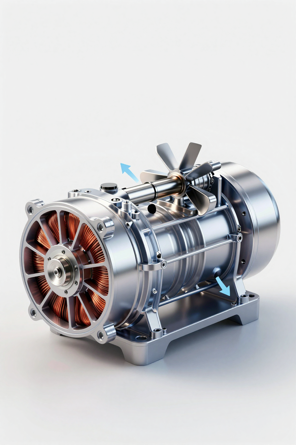
The core differentiator of a variable speed dc compressor is the integration of a BLDC motor and an inverter driver board. Unlike brushed motors that rely on mechanical commutation, BLDC motors use electronic commutation, where the driver board switches the phase currents based on rotor position feedback (often via Back-EMF or Hall sensors).
Proportional Capacity Modulation
The cooling capacity (BTU/hr or Watts) of a vapor compression system is directly proportional to the mass flow rate of the refrigerant. In a variable speed dc compressor, the mass flow rate is controlled by the rotational speed (RPM) of the compressor.
Logic: If the sensor detects the temperature rising 0.5°C above setpoint, the controller commands a slight RPM increase (e.g., from 2000 to 2200 RPM). If the temperature spikes 5°C, the controller ramps to maximum RPM (e.g., 4500 RPM). This creates a feedback loop where cooling supply matches heat load demand dynamically.
The Role of the Driver Board
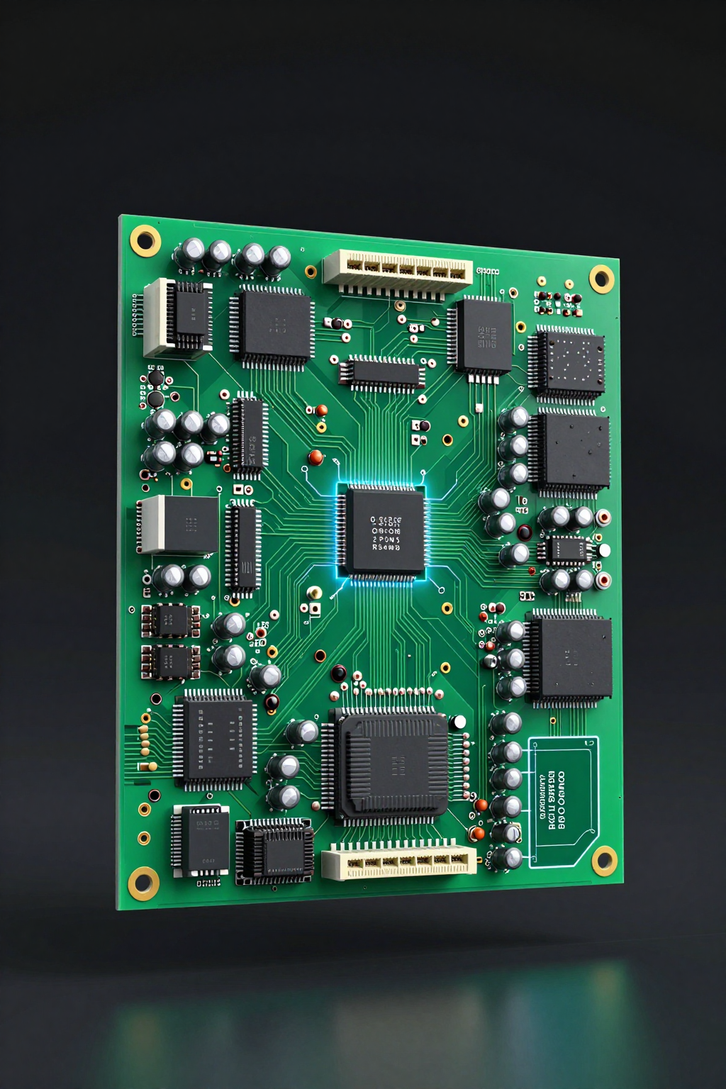
The variable speed dc compressor cannot operate directly from a DC power supply; it requires a dedicated driver board (PCB). This board performs three critical functions:
- Commutation: Converting the DC input (12V/24V/48V) into the pulsed 3-phase AC waveform required by the BLDC motor windings.
- Speed Control: Interpreting an external signal (0-5V, PWM, or RS485) to adjust the frequency of the output waveform, thereby controlling RPM.
- Protection: Monitoring for over-current, over-voltage, and compressor stall conditions.
Performance Data & Verified Specs
Arctic-tek’s research into miniature thermal management highlights specific performance envelopes for the variable speed dc compressor. The following data points are derived from verified testing of the Micro DC Aircon series and Miniature DC Compressor units.
| Parameter | Specification Range (Series Dependent) | Engineering Implication |
|---|---|---|
| Nominal Voltage | 12V / 24V / 48V | Direct integration with battery banks and DC buses without inverters. |
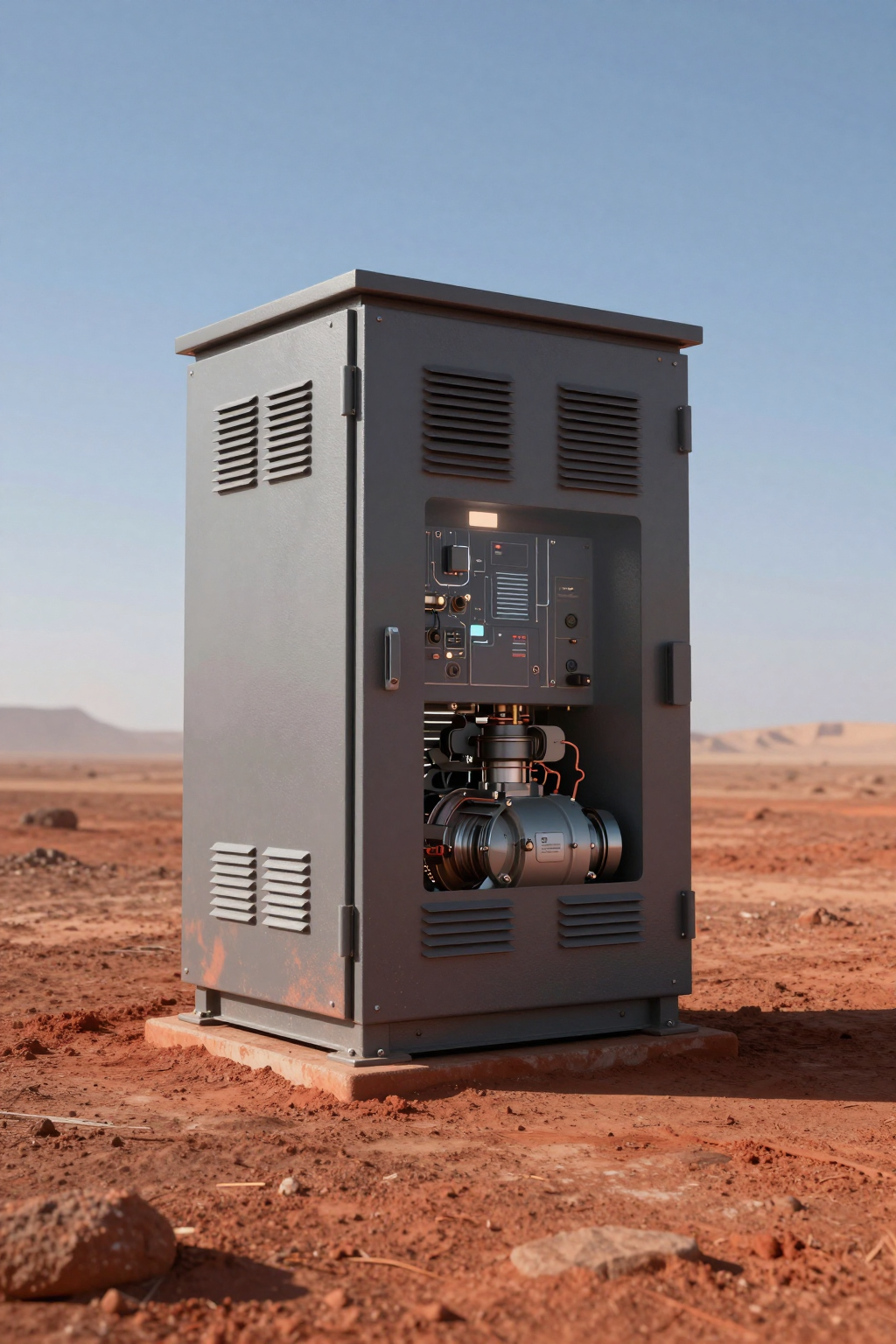
| Cooling Capacity | 100W – 900W | Scalable for micro-enclosures up to larger telecom cabinets. |
| Refrigerants | R134a / R290 / R1234yf | Compliance with GWP regulations and thermodynamic efficiency requirements. |
| Compressor Type | BLDC Inverter Rotary | Enables the variable speed operation and high volumetric efficiency. |
| Speed Control | Variable (Inverter Driven) | Allows for precise temperature holding (±0.5°C or better depending on logic). |
For example, the QX1902VDL (24V) and QX1903VDL (48V) are miniature DC compressors that exemplify this technology. They do not simply run at a single speed; they respond to the driver’s frequency output. Similarly, the DV1920E-AC (24V, 450W) Micro DC Aircon unit integrates this variable speed dc compressor technology to provide a complete cooling solution that modulates based on enclosure temperature.
The ability to utilize a variable speed dc compressor allows these units to achieve a Coefficient of Performance (COP) that exceeds fixed-speed equivalents, particularly at partial loads where the compressor runs at lower, more efficient RPMs.
Field Implementation Checklist: Best Practices
Integrating a variable speed dc compressor requires more than just piping refrigerant. It requires a systems engineering approach to control logic and electrical integration. Below is a checklist for OEM engineers designing these systems.
Electrical Integration
- Cable Sizing: Even with soft-start, ensure cables are sized for the maximum rated current (plus safety margin) to prevent voltage drop at the driver board input.
- EMI Shielding: The high-frequency switching of the inverter driver can generate electromagnetic interference. Use shielded cables for the compressor phases and keep signal wires (0-5V/PWM) separate from power lines.
- Power Supply Stability: Ensure the DC power source (battery or PSU) can handle rapid load changes without sagging below the driver’s cut-off voltage.
Thermal & Mechanical
- Oil Return: Running a variable speed dc compressor at very low RPM for extended periods can hinder oil return to the compressor. Implement logic to periodically ramp up speed (oil recovery cycle) if low-load operation persists.
- Vibration Isolation: While rotary compressors are balanced, variable speeds can pass through system resonance frequencies. Use appropriate rubber grommets and test across the full RPM range.
- Airflow Management: Match the variable compressor speed with variable fan speeds (condenser and evaporator) for maximum efficiency. A static fan with a modulating compressor is a missed optimization opportunity.
Control Logic
- PID Tuning: Do not use simple bang-bang control. Implement a PID loop that outputs a speed command proportional to the error (Set Temp – Actual Temp).
- Sensor Placement: Place the control sensor in the return air path for the most accurate representation of the internal load.
Expert Field FAQ
Q: Can I run a variable speed dc compressor at a fixed speed if I don’t need modulation?
A: Yes. Most driver boards allow you to set a fixed resistance or voltage on the speed control pin to lock the compressor at a specific RPM (e.g., max capacity). However, you lose the efficiency and stability benefits of the variable speed dc compressor.
Q: What happens to the IP rating of the system during integration?
A: The compressor itself is hermetically sealed, but the driver board is often an open PCB. It must be mounted inside a rated enclosure (IP54 or higher) to protect it from dust and moisture. Arctic-tek’s Micro DC Aircon units typically integrate the board within a protected housing.
Q: How does a variable speed dc compressor handle high ambient temperatures?
A: Models like the QX1902VDL-T are designed for tropical conditions. The variable speed allows the compressor to run at higher RPMs to reject heat in extreme ambients, provided the condenser is sized correctly to prevent high-pressure trips.
Q: Is the driver board universal for all variable speed dc compressors?
A: No. The driver board must be matched to the specific motor parameters (inductance, resistance, back-EMF constant) of the compressor. Using a mismatched board can result in poor efficiency, stalling, or motor damage.
Q: What is the minimum stable speed for these compressors?
A: It varies by model, but typically around 1800-2000 RPM. Below this, lubrication becomes a concern, and the motor efficiency drops. The control logic should prevent the variable speed dc compressor from commanded speeds below this floor.
Q: Does the variable speed dc compressor eliminate the need for a thermostat?
A: It eliminates the mechanical thermostat. You still need a temperature sensor (thermistor) and a controller (microcontroller or PLC) to read the temp and send the speed signal to the compressor driver.
Conclusion & System Logic
The transition from fixed-speed to variable-speed cooling is not merely a trend; it is a response to the increasing demands for precision, efficiency, and mobility in industrial hardware. The variable speed dc compressor offers a solution that aligns cooling supply with thermal demand, eliminating the destructive cycles of hysteresis and inrush current.
For OEM engineers, the integration of a variable speed dc compressor—whether as a standalone component like the QX series or within a pre-packaged solution like the DC condensing unit—requires a shift in design thinking. It demands attention to control logic, signal integrity, and thermal dynamics. However, the return on this engineering investment is a system that runs quieter, lasts longer, and protects critical payloads with a precision that fixed-speed systems simply cannot match.
When uptime is critical and power is finite, the logic of the variable speed dc compressor is undeniable. Consult with the Arctic-tek engineering team to determine the correct thermal sizing and driver integration for your specific application.


0 条评论