Angle Lock: The decision is between an open-loop filter fan and a closed-loop active cooling system. The primary failure modes are contaminant ingress causing electronic shorts and thermal shutdown of VFDs during peak production. The dominant constraint is maintaining a sealed NEMA/IP-rated enclosure in a high-particulate environment.
Why High-Dust Environments Demand Closed-Loop Control Panel Cooling
A variable frequency drive (VFD) trips on an over-temperature fault in the middle of a critical production run. The culprit is not the drive itself, but a seemingly minor component: a filter fan on the control cabinet, now completely clogged with industrial dust and oil mist. The cost of this failure is measured in hours of unplanned downtime, lost product, and the risk of permanent damage to expensive electronics. For automation engineers and system integrators, this scenario is both common and preventable.
The default approach of using fans and filters for enclosure cooling is a liability in any environment that isn’t perfectly clean. Once dust, moisture, or chemical vapors are present, open-loop systems create more problems than they solve. By the end of this article, you will be able to identify the precise operational threshold where passive or open-loop cooling becomes untenable, and a robust, active thermal management strategy is the only viable path forward. In this analysis, we prioritize long-term system reliability and component longevity over minimal upfront cost, because the price of production downtime in automated manufacturing far exceeds the investment in proper closed-loop control panel cooling.
Deployment Context: Where Open-Loop Systems Fail
Theory gives way to reality on the factory floor. Two common scenarios illustrate the limits of conventional cooling methods when faced with industrial contaminants.
Scenario A: CNC Machining Center
A compact control panel is integrated into a multi-axis CNC milling machine. The ambient air is a constant aerosol of fine metallic dust and cutting fluid mist. The original design incorporated a standard filter fan assembly to cool the PLC and multiple servo drives. Within the first month of operation, the maintenance team found the filter saturated weekly. Technicians couldn’t keep up with the cleaning schedule, leading to progressively higher internal temperatures. Eventually, a servo drive overheated and failed, halting a high-value machining job. The core constraint was the high concentration of mixed, conductive contaminants that no filter could practically manage.
Scenario B: Textile Processing Plant
In a weaving facility, a control cabinet manages a series of industrial looms. The air is saturated with airborne lint and synthetic fibers, which have an insulating, blanket-like quality. A thermoelectric (Peltier) cooler was initially chosen. However, the cooler’s external heat sink fins, essential for rejecting heat, became completely clogged with a thick layer of lint. This insulation caused the thermoelectric unit to fail, leading to a cascade of overheating within the panel on a hot summer day. The constraints were the insulating nature of the contaminant and a high ambient factory temperature exceeding 40°C.
Common Failure Modes & System Constraints
In environments with high dust, relying on open-loop cooling introduces predictable failure points. Understanding these symptoms and their root causes is the first step in designing a more resilient system.
- Symptom: Frequent VFD/Servo Drive Over-Temp Faults → Cause: Clogged air filters severely restricting airflow → Why it matters: Halts production instantly and repeated thermal cycling can degrade and permanently damage power electronics.
- Symptom: Unpredictable PLC Logic Errors or System Freezes → Cause: Internal cabinet temperature exceeding the processor’s safe operating limits → Why it matters: Can lead to erratic machine behavior, creating safety risks, corrupting data, and requiring a full system restart.
- Symptom: Corroded Terminal Blocks and PCB Traces → Cause: Humid, corrosive, or conductive dust drawn directly into the panel by fans → Why it matters: Creates intermittent electrical faults that are notoriously difficult to diagnose and significantly shortens the lifespan of all internal components.
- Symptom: Oily or Grimy Film Coating Components → Cause: Oil mist from nearby machinery bypassing inadequate filters → Why it matters: This film traps dust, impairs natural heat dissipation from component surfaces, and can increase fire risk.
- Symptom: Premature Power Supply Failure → Cause: Capacitors and regulators overheating due to insufficient clean airflow → Why it matters: A failed power supply brings the entire system down and can be a costly emergency replacement.
- Symptom: Compromised NEMA/IP Rating → Cause: The very existence of vents and cutouts for fans and filters → Why it matters: It voids the enclosure’s environmental protection rating, potentially failing safety audits and exposing sensitive electronics to washdowns or airborne particles the enclosure was meant to block.
- Symptom: High Maintenance Overhead → Cause: A constant, demanding schedule of filter inspection and replacement → Why it matters: This increases operational costs, consumes technician time, and relies on perfect human discipline—which is often the first thing to fail in a busy plant.
Engineering Fundamentals: The Closed-Loop Advantage
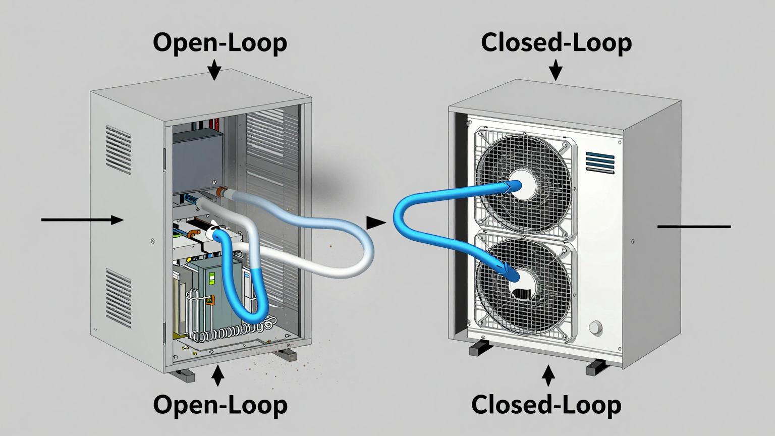
The core principle of effective high dust enclosure cooling is environmental isolation. A control panel is, by design, a sealed box meant to protect sensitive electronics from a harsh external world. The moment you cut a hole for a fan, you break that seal.
A closed-loop control panel cooling system restores this fundamental principle. It operates by creating two completely separate air circuits. The internal circuit circulates air within the enclosure, drawing heat away from components like PLCs, VFDs, and power supplies. This heated internal air passes over the cold side of the cooling unit (the evaporator). The heat is absorbed into a refrigerant and transferred to the external circuit, where it is rejected into the ambient factory environment by the hot side of the unit (the condenser). The internal air, now cooled, is sent back to the components. No outside air ever enters the enclosure.
This approach maintains the integrity of the enclosure’s NEMA or IP rating, ensuring that dust, moisture, and chemicals cannot get in.
The Critical Misconception
A common but flawed piece of logic is that “a bigger fan will solve the overheating problem.” This is incorrect. A more powerful fan simply accelerates the failure process. It pulls in a higher volume of contaminated air, clogging the filter faster and depositing more dust and oil onto your critical components. Furthermore, a fan can never cool the internal air to a temperature below the ambient factory air. If the factory is 40°C, the best a fan can ever hope to achieve is 40°C inside the panel, which is often too hot for sensitive electronics under full load. True cooling requires active heat removal, not just air exchange.
Specification Gateway for Active Cooling Units
When selecting an active cooling solution like a miniature DC air conditioner, the specifications provide a clear roadmap. For effective high dust enclosure cooling, focus on these key parameters:
- Nominal Cooling Capacity (Watts): This is the most critical spec. It must be greater than the total heat load generated by all components inside the enclosure. Always add a safety margin of 20-25% to account for factors like solar load or future component additions.
- DC Voltage: The unit must be compatible with the available power bus inside your control panel. 24VDC is a common standard in industrial automation, but 12V and 48V options are also available for specific applications.
- Physical Dimensions & Weight: The cooler must physically fit on or inside your enclosure without obstructing critical access points or violating clearance requirements.
The table below shows example specifications for the Rigid Chill Micro DC Aircon series, which are designed for these compact applications.
| Model (Example) | Voltage | Nominal Cooling Capacity | Refrigerant |
|---|---|---|---|
| DV1920E-AC (Pro) | 24V DC | 450W | R134a |
| DV3220E-AC (Pro) | 24V DC | 550W | R134a |
| DV1930E-AC (Pro) | 48V DC | 450W | R134a |
| DV1910E-AC (Pro) | 12V DC | 450W | R134a |
| General Series Range | 12V / 24V / 48V | 100W–900W | Varies by model |
Engineering Selection Matrix: Logic Gates for System Design
An experienced engineer navigates the selection process through a series of logical gates. If your application passes through any of these gates, a closed-loop system is no longer a luxury—it’s a design requirement.
Gate 1: The Sealing Mandate
- Constraint Gate: Required NEMA/IP Rating vs. Ambient Contaminant Type.
- Decision Trigger: If the operating environment contains conductive dust (metal shavings), corrosive vapors, or requires regular high-pressure washdowns (requiring a NEMA 4/4X or IP66 rating), then any solution with an air exchange vent is immediately disqualified.
- Engineering Resolution: The enclosure must remain hermetically sealed. This mandates the use of a non-invasive thermal solution that does not exchange air, such as a Micro DC Aircon.
- Integration Trade-off: This path requires a higher initial capital investment and a dedicated power draw compared to a fan. However, it is the only way to preserve the enclosure’s protective rating and eliminate contaminant-driven failures.
Gate 2: The Thermal Delta Threshold
- Constraint Gate: Required Internal Temperature vs. Maximum Ambient Factory Temperature.
- Decision Trigger: If the maximum allowable internal temperature for your most sensitive component (e.g., a processor rated for 45°C) is lower than the peak ambient temperature the factory experiences (e.g., 50°C next to a furnace), then passive and air-exchange solutions are physically incapable of meeting the requirement.
- Engineering Resolution: Active refrigeration is non-negotiable. A vapor-compression air conditioning system is required to actively pump heat out of the enclosure and create a negative temperature differential (i.e., make the inside cooler than the outside).
- Integration Trade-off: This introduces a compact refrigeration circuit. The benefit is the ability to maintain a stable, cool internal setpoint, ensuring zero derating of electronics even as external temperatures fluctuate wildly.
Gate 3: The Heat Load Density Gate
- Constraint Gate: Total Internal Heat Load (Watts) vs. Enclosure Surface Area (m²).
- Decision Trigger: In modern, compact control panels, the density of high-power components like multiple VFDs, large power supplies, and industrial PCs is very high. If the calculated total heat load in watts exceeds the enclosure’s ability to naturally dissipate that heat through its own walls, the internal temperature will rise uncontrollably.
- Engineering Resolution: A thorough heat load calculation is mandatory. The selected closed-loop control panel cooling unit must have a nominal cooling capacity that exceeds this calculated load by a safety margin of at least 20%.
- Integration Trade-off: Requires upfront engineering diligence to audit the power consumption of every component. The result is a correctly sized thermal management system that prevents overheating under 100% duty cycle conditions.
Implementation & Verification Checklist
Proper installation is just as critical as proper selection. Follow this checklist to ensure performance and reliability.
- Mechanical Integration
- Mounting Surface: Ensure the chosen mounting location on the enclosure is flat, structurally sound, and can support the unit’s weight. Use all provided mounting hardware.
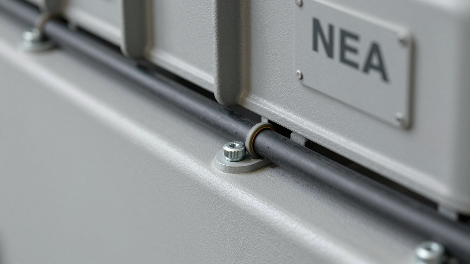
- Gasket Seal: This is the most critical step for preserving the seal. Clean both the enclosure surface and the unit flange. Apply the gasket carefully and tighten the mounting bolts in a star pattern to ensure even compression. A perfect seal is paramount.
- Airflow Integrity: Verify that the internal and external fans are completely unobstructed. Leave at least 10-15 cm of clearance for the external air intake and exhaust. Inside, ensure that cooled air can circulate freely around the hottest components.
- Electrical Connection
- Power Source: Connect the unit to a dedicated DC circuit from a reliable power supply. Use the appropriate wire gauge to handle the maximum current draw without voltage drop.
- Circuit Protection: Install an appropriately rated fuse or circuit breaker in-line with the positive lead, as specified in the installation manual. This protects both the cooling unit and your power system.
- Wiring Practices: Route all wiring neatly, away from sharp edges, vibration sources, and high-temperature components. Ensure all terminal connections are secure.
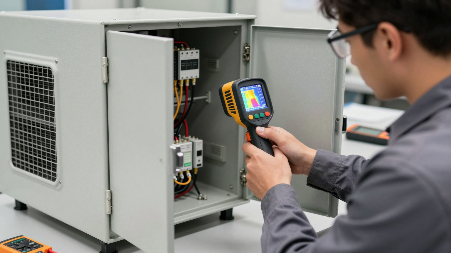
- Thermal Validation
- Sensor Placement: For accurate monitoring, place an independent, calibrated thermocouple or temperature sensor inside the enclosure. Position it near the top of the cabinet (where heat collects) but away from the direct cold air outlet of the cooling unit.
- Acceptance Testing: After installation, close the cabinet door and run the enclosed equipment under full, real-world load. Monitor the internal temperature to confirm that it stabilizes at or below your target setpoint. The ultimate test is to perform this on the hottest day of the year.
- Maintenance Plan
- External Coil Inspection: The key advantage of a closed-loop system is that the inside stays clean. However, the external (condenser) coils can still collect ambient dust. Periodically inspect these coils and clean them with compressed air (blown from the inside out) to maintain peak heat rejection efficiency.
- Gasket Check: During annual preventative maintenance, visually inspect the mounting gasket for any signs of cracking, brittleness, or damage that could compromise the seal.
Frequently Asked Questions (FAQ)
- What is the main difference between a filter fan and closed-loop cooling?
- A filter fan is an open-loop system that pulls contaminated ambient air into your enclosure to cool components. A closed-loop system completely isolates the internal air, cooling and recirculating it without introducing any outside contaminants, thus preserving the sealed integrity of the panel.
- My panel is IP66 rated. How can I cool it without compromising the seal?
- Closed-loop air conditioners are designed for this exact purpose. They mount through a precise cutout in the enclosure wall, and a compression gasket creates a watertight and dust-tight seal between the unit and the panel, maintaining the original IP66 rating.
- Will a miniature air conditioner create condensation inside my panel?
- When a unit is sized correctly, it cools the internal air but keeps the surface temperature of the electronic components above the dew point of that air, preventing condensation from forming on them. Any moisture that condenses on the unit’s internal evaporator coil is managed by the unit and typically evaporated to the outside environment.
- How does direct sunlight or proximity to an oven affect the cooling unit?
- Radiant heat sources like direct sun or an industrial oven add a significant external heat load to the enclosure. This load must be calculated and added to the internal heat load when sizing the cooling unit. You will likely need a unit with a higher cooling capacity to compensate.
- What is the most important measurement I need before selecting a cooler?
- The single most critical value is the total internal heat load in watts, generated by all components within the enclosure. The second and third are the maximum expected ambient temperature and the required internal temperature.
- How can I validate that the closed-loop control panel cooling system is working correctly?
- The best method is empirical measurement. Use a thermal probe to monitor the internal air temperature while the system is running under full production load. It should remain stable and well below the maximum operating temperature of your most sensitive component.
- Are these vapor-compression units better than thermoelectric (Peltier) coolers?
- For most industrial applications with significant heat loads, vapor-compression systems are far more efficient. They have a much higher Coefficient of Performance (COP), meaning they provide more watts of cooling for each watt of electricity consumed, making them a better choice for cooling anything beyond a few dozen watts.
Conclusion: The Right Tool for a Demanding Job
The decision to use a closed-loop control panel cooling system is a strategic one based on a clear understanding of the operating environment. This approach, particularly using miniature DC air conditioning, is the most robust and reliable solution when system uptime is critical in environments contaminated with dust, moisture, or chemicals. It is the definitive choice whenever an enclosure’s NEMA or IP rating must be preserved, or when the internal temperature must be actively maintained below the ambient factory temperature.
While open-loop filter fans have a place in clean, temperature-controlled environments with low heat loads, they represent a significant and unnecessary risk on the modern factory floor. Investing in a properly sealed and actively cooled enclosure is a direct investment in production consistency and equipment longevity.
If you are designing control systems for challenging industrial applications, ensuring robust thermal management is a foundational step. Contact the Rigid Chill engineering team to discuss your project’s specific requirements, including heat load calculations, power constraints, and custom mounting for your high dust enclosure cooling needs.


0 条评论