Angle Lock: The critical decision is moving from simple air circulation to active, closed-loop cooling to resolve localized hot spots. The primary failure modes are catastrophic failure of a single overheated component and the gradual, premature aging of electronics in one zone. This decision is dominated by the constraint of maintaining a sealed enclosure, which forbids simple ventilation.
Why Temperature Uniformity in a Sealed Cabinet is Critical for Preventing Uneven Component Aging
Your team designed the system to operate within a safe average internal temperature. The thermal models checked out. Yet, you’re seeing inexplicable field failures—power supplies dying years ahead of their rated lifespan, or processors resetting for no apparent reason. The culprit is often not the average temperature, but the thermal gradients within the enclosure. A single, persistent hot spot can silently degrade a critical component, leading to costly warranty claims, system downtime, and damage to your reputation. Simply circulating hot air with fans isn’t a solution; it’s a delay tactic.
By the end of this article, you will be able to determine the precise engineering trigger for moving from passive or fan-based cooling to an active, closed-loop air conditioning solution. We will explore how to diagnose and resolve thermal imbalances to ensure long-term system reliability. In this analysis, we prioritize eliminating thermal gradients over simply lowering the average internal temperature, because a single hot spot can undermine the reliability of the entire system.
Deployment Context: Where Uniformity Fails
Theoretical models often miss the harsh realities of deployment. Here are two common scenarios where a focus on average temperature leads to failure.
Scenario A: Roadside Telecom Cabinet
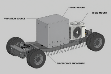
A sealed NEMA-4 cabinet housing 5G radio and processing hardware is mounted on a pole, exposed to direct solar load. Internal fans circulate air to prevent heat buildup. However, due to natural convection, the top-mounted power supply unit (PSU) consistently operates 15°C hotter than the baseband unit located at the bottom. This localized heat concentration accelerates the aging of the PSU’s capacitors, leading to premature failures within two years, despite a system design life of ten. The core constraint is the combination of a sealed enclosure and a high, variable external heat load that fans alone cannot overcome.
Scenario B: Factory Floor Automation Controller
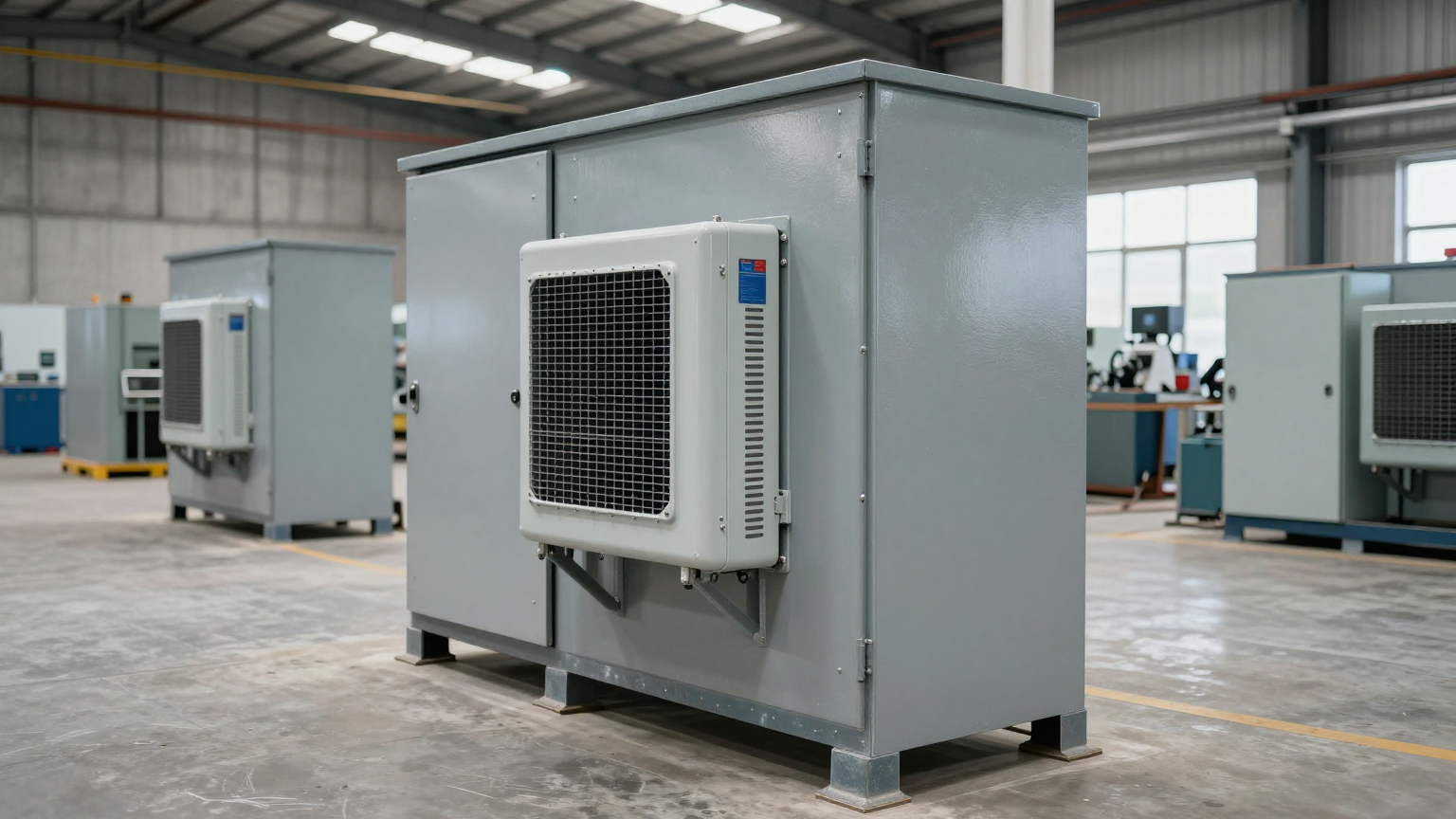
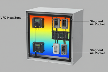
An industrial control cabinet on a manufacturing line contains PLCs, I/O modules, and a high-power Variable Frequency Drive (VFD). The VFD is a significant and concentrated heat source. While the cabinet’s average temperature remains within the 40°C specification, the PLC mounted directly beside the VFD experiences intermittent processing faults during peak production hours. The root cause is radiative heat from the VFD creating a microclimate that pushes the PLC’s processor beyond its stable operating limit. The constraint here is the high thermal density of specific components and the absolute need for a sealed design to protect against conductive dust and washdown cycles.
Common Failure Modes & System Constraints
Focusing on hot spots reveals the true risks to long-term reliability. These issues often manifest long after initial commissioning, making them difficult to diagnose.
- Symptom: Intermittent system resets or data errors → Cause: A CPU or FPGA exceeds its maximum junction temperature under computational load → Why it matters: Causes unpredictable system downtime and potential data corruption.
- Symptom: Power supply failures years before expected MTBF → Cause: Electrolytic capacitors and MOSFETs located in a hot zone degrade exponentially faster → Why it matters: Results in expensive field service calls and erodes system availability.
- Symptom: Sensor drift and inaccurate analog readings → Cause: Precision analog components operate outside their thermally stable range → Why it matters: Compromises process control, data integrity, and overall system performance.
- Symptom: Noticeably reduced battery backup runtime → Cause: Persistently elevated temperatures permanently reduce the chemical capacity and lifespan of backup batteries → Why it matters: Critical power backup becomes unreliable when it’s needed most.
- Symptom: Inconsistent performance between identical deployed units → Cause: Minor variations in component layout create different hot spot profiles from one cabinet to the next → Why it matters: Complicates remote diagnostics and undermines customer confidence.
- Symptom: Warped PCBs or premature solder joint fatigue → Cause: Extreme and repeated thermal cycling localized to one area of a board → Why it matters: Leads to hard-to-trace intermittent connections and eventual hardware failure.
Engineering Fundamentals: Beyond Simple Airflow
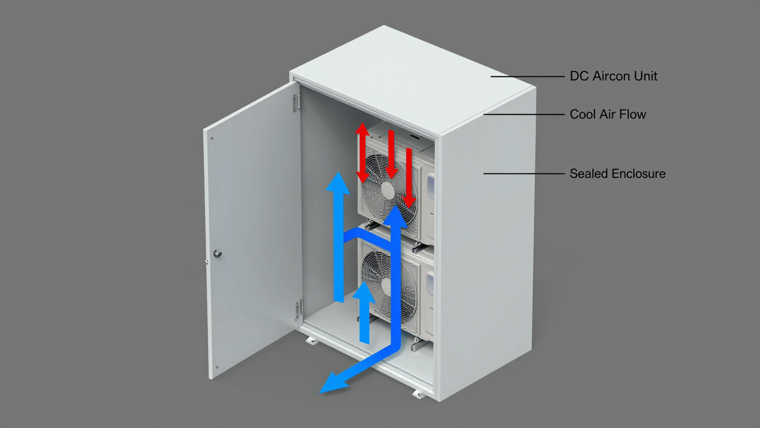
The core engineering challenge in a sealed cabinet is that you cannot simply vent hot air. Any heat generated inside stays inside unless it is actively removed through the cabinet walls. A fan can stir the internal air, reducing the intensity of a hot spot, but it cannot remove the heat energy from the closed system. This inevitably leads to heat stratification, where hot air rises and creates a permanent, high-temperature zone at the top of the enclosure.
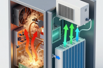
An active, refrigerant-based cooling system, such as a Micro DC Aircon, fundamentally changes the thermal path. It creates a true closed loop for heat removal. The unit strategically pulls the hottest air from a target zone (e.g., near a VFD or at the top of the cabinet), forces it across a cold evaporator coil to extract the heat energy, and then exhausts chilled, dehumidified air back into the cabinet, typically at a low point to promote circulation. This forced convection actively breaks up thermal gradients and ensures a much higher degree of temperature uniformity in the sealed cabinet.
Common Misconception: “My average cabinet temperature is 45°C, and my components are rated for 70°C, so I have plenty of margin.”
Correction: The average air temperature is one of the least important metrics for reliability. The surface temperature of your most stressed component is what truly matters. An average air temperature of 45°C can easily hide a processor running at 85°C or a power resistor hitting 110°C. Managing the peak temperature of the hottest component is the only way to prevent uneven component aging and ensure system longevity.
Key Specifications for Active Cooling Selection
When passive methods are insufficient, an engineer must evaluate active cooling solutions based on several go/no-go criteria. These specifications are critical for ensuring the chosen solution can enforce thermal uniformity under worst-case conditions.
- Cooling Capacity (Watts): This is the starting point. The unit’s capacity must be greater than the total heat load generated by all internal components. Always design for the maximum continuous load, not the average.
- Airflow Volume (CFM or M³/hr): Sufficient airflow is needed to circulate the air within the cabinet multiple times per minute. This ensures the chilled air reaches all corners and prevents the formation of stagnant, hot pockets of air.
- Thermal Delta (ΔT): This defines the cooler’s ability to maintain a set internal temperature while the external ambient temperature rises. A robust solution must be able to maintain a cool interior even when the outside environment is significantly hotter.
- Physical Footprint & Volumetrics: The cooling unit must physically fit within the often-cramped confines of an electronics enclosure without obstructing maintenance access or critical airflow paths.
- DC Voltage and Power Consumption: The unit must be compatible with the system’s native DC power bus (e.g., 12V, 24V, or 48V) and its power draw must fit within the overall system power budget, especially the PSU’s capacity.
- Control System Integration: Modern cooling units feature integrated driver boards with variable-speed controls. This allows the cooling performance to ramp up and down based on real-time thermal load, improving efficiency and reducing mechanical stress on the compressor and fans.
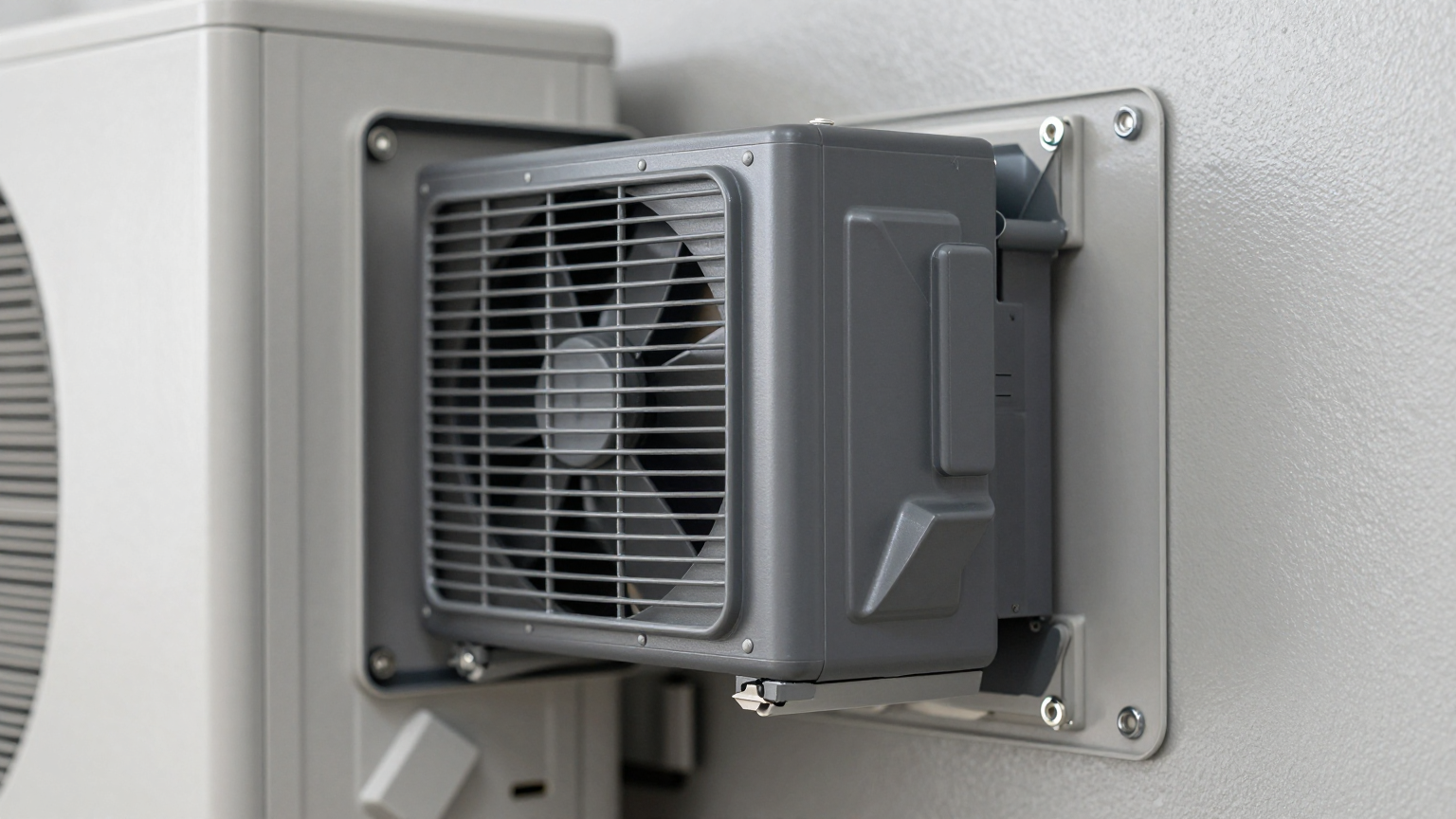
- Mounting and Sealing Integrity: The unit must be designed to mount directly to the cabinet wall with a gasket system that preserves the original NEMA or IP rating of the enclosure.
Engineering Selection Matrix: Logic Gates for Thermal Control
An engineer must pass through several logic gates to arrive at the correct thermal management strategy. Moving through these gates clarifies the trade-offs and justifies the shift to a more robust solution.
Gate 1: The Airflow vs. Heat Removal Gate
- Constraint Gate: Internal circulation fans are running at maximum speed, but the temperature of critical components continues to climb and exceed safe limits.
- Decision Trigger: If aggressive internal air circulation alone cannot keep the hottest component below its maximum operating temperature, the problem is no longer about airflow—it’s about an inability to remove heat energy from the sealed system.
- Engineering Resolution: The design must evolve from simple air movers (fans) to an active heat removal device. A vapor-compression system like a compact DC air conditioner is the direct solution.
- Integration Trade-off: This adds a new load to the DC power bus and requires a cutout in the enclosure wall. However, it is the only method that physically transports thermal energy out of the sealed environment, ensuring component survival.
Gate 2: The Average vs. Peak Temperature Gate
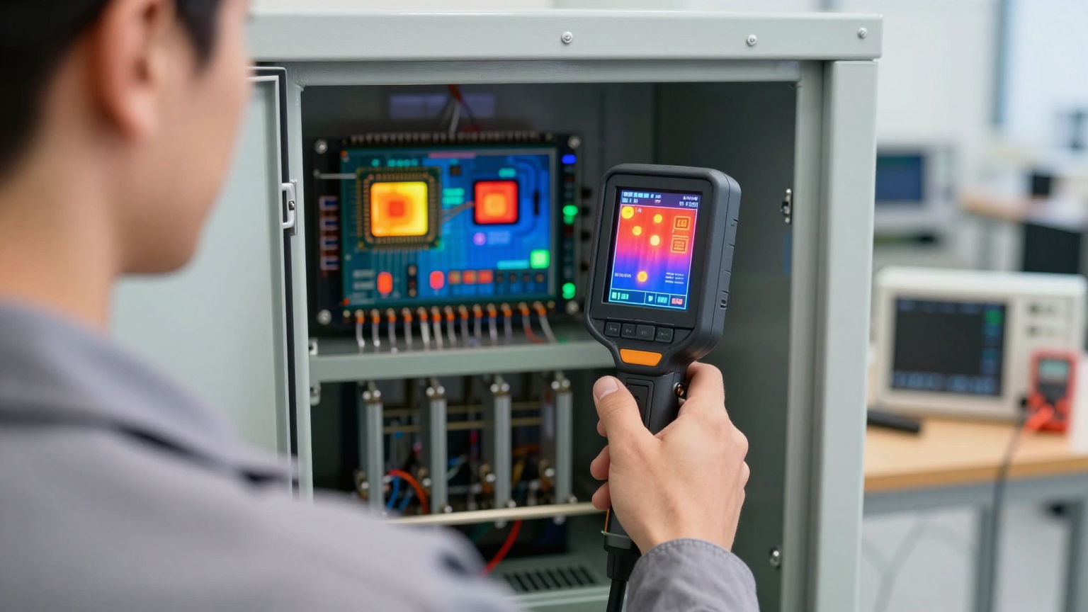
- Constraint Gate: The single ambient temperature sensor in the cabinet reads an acceptable 40°C, but thermal imaging or direct measurement reveals a specific FPGA is operating at 85°C.
- Decision Trigger: If the temperature difference (delta) between the average internal air and the hottest component surface exceeds a predefined threshold (e.g., >20°C), passive and simple fan-based methods have failed to achieve temperature uniformity in a sealed cabinet.
- Engineering Resolution: Implement a directed or zoned cooling strategy. A Micro DC Aircon can be positioned to draw hot air directly from the heat source and inject cold air to bathe the critical component, directly addressing the microclimate.
- Integration Trade-off: This may require more thoughtful placement of the cooling unit or simple internal baffles to guide airflow. The benefit is a direct solution to the root cause of uneven component aging.
Gate 3: The Sealed Enclosure vs. Ambient Environment Gate
- Constraint Gate: The cabinet must maintain an IP55 or higher rating to protect against environmental hazards like dust or moisture, and it is deployed where ambient temperatures can be high.
- Decision Trigger: If the external ambient temperature can meet or exceed the desired maximum internal temperature, then a thermoelectric cooler or a simple air-to-air heat exchanger is not a viable solution. These devices can only approach the ambient temperature; they cannot cool below it.
- Engineering Resolution: A refrigerant-based, vapor-compression air conditioner is required. This is the only mainstream technology that can create a temperature delta where the inside of the cabinet is actively cooled to a temperature below the outside world, all while maintaining a perfect seal.
- Integration Trade-off: While having a higher initial cost and complexity than a heat exchanger, an active air conditioner provides deterministic thermal control. This performance guarantee is non-negotiable for high-reliability systems deployed in uncontrolled environments.
Implementation and Verification Checklist
Proper integration is as important as selecting the right hardware. Follow this checklist to ensure performance and reliability.
- Mechanical Integration
- Mounting: Securely fasten the cooling unit to the cabinet wall, using vibration dampeners if required by the application.
- Sealing: Use the manufacturer-supplied gasket and follow specified torque patterns for all mounting bolts to maintain the enclosure’s environmental rating.
- Airflow Integrity: Ensure the cool air outlet and hot air return are completely unobstructed. Use simple sheet metal baffles to direct cool air toward known hot spots and ensure hot air can return to the unit.
- Electrical Integration
- Power Source: Connect the unit to a DC power rail with sufficient capacity for both inrush and continuous current draw. Use dedicated, appropriately gauged wiring with proper overcurrent protection (fusing).
- Control Signals: Route any thermostat or remote control wiring away from high-noise sources like VFD power lines or switching supplies.
- Thermal Validation
- Sensor Placement: For validation, place thermocouples directly on the heat sinks of critical components (CPUs, FPGAs, PSUs), not just in the open air. This is the only way to measure true hot spot temperatures.
- Acceptance Test: Operate the entire system at its maximum expected electrical load within a thermal chamber set to the worst-case ambient temperature. Log component temperatures to confirm that all critical hot spots remain well within their specified operating limits. This is the final proof of a successful design.
- Maintenance Planning
- Access: Install the unit so that any external heat sink fins and fans are accessible for periodic inspection and cleaning, as dust buildup can degrade performance.
- Inspection Schedule: For harsh environments, establish a recurring maintenance task to check for debris on heat exchangers and verify fan operation.
Frequently Asked Questions (FAQ)
Should I just use a more powerful fan instead of an air conditioner?
A fan only circulates air; it cannot remove heat from a sealed system. If the internal heat load is causing the entire system to heat up, a fan will only succeed in making the hot spots slightly less hot while raising the average temperature of everything else. An air conditioner is required to physically remove the heat energy.
How does a cooling unit affect my cabinet’s IP/NEMA rating?
Properly designed cabinet coolers are built to integrate seamlessly. They are mounted with a compression gasket that, when installed correctly, maintains the original environmental seal of the enclosure. The internal and external air paths are completely separate.
Will an air conditioner create condensation inside my cabinet?
Because a closed-loop air conditioner cools the existing internal air and does not introduce new, moist air from the outside, it actually dehumidifies the enclosure. As the internal air passes over the cold coil, moisture condenses and is managed (typically evaporated) on the external side. This protects electronics from corrosion.
What is the impact of direct sunlight on the cooling system?
Direct solar radiation adds a significant external heat load to the cabinet walls. This load must be factored into your total thermal calculation. When selecting a cooling unit, you must add the solar load (which can be several hundred watts) to the internal electronic heat load to size the unit correctly.
What is the first thing I must measure before selecting a cooling solution?
You need two critical pieces of data: 1) The total internal heat load in watts (the sum of all power consumed by the electronics). 2) The actual surface temperature of your hottest, most critical component when the system is running under its maximum real-world load.
How do I validate that I’ve solved the temperature uniformity problem after installation?
The best method is to use a thermal imaging camera or multiple thermocouples placed directly on components. Run the system at full load and compare the temperatures of the hottest and coolest components. A small delta between them confirms you have achieved good thermal uniformity.
Why is uneven component aging a bigger risk than a simple overheat shutdown?
An overheat shutdown is a predictable event that protects the hardware. Uneven component aging is a silent, insidious failure mode. It causes components to fail prematurely and unpredictably in the field, leading to reliability issues that are extremely difficult and expensive to diagnose and resolve after deployment.
Conclusion: From Heat Management to System Reliability
The transition from managing average temperature to enforcing temperature uniformity in a sealed cabinet is a crucial step in designing high-reliability systems. While fans and heat sinks have their place, they are insufficient when faced with high-density heat loads, sealed enclosure requirements, and challenging ambient environments. Active, closed-loop cooling is the definitive engineering solution when component longevity and predictable performance are non-negotiable.
This approach is the best fit when a sealed enclosure is mandatory, internal heat loads are significant or concentrated, and long-term reliability is the primary design driver. It is likely unnecessary for low-power systems in vented enclosures within climate-controlled rooms. Achieving true thermal uniformity is a system-level challenge. If you are contending with hot spots or premature field failures, our engineering team can help analyze your thermal profile and configure a cooling solution based on your specific enclosure geometry, power constraints, and environmental challenges.
0 条评论