Angle: The critical decision is selecting the right mounting strategy and vibration isolation for a compact DC air conditioner. Common failure modes include refrigerant line fracture from metal fatigue and compressor bearing failure from excessive g-force. The dominant constraint is managing mechanical shock and persistent, multi-axis vibration in mobile or industrial settings.
A Guide to Micro DC Aircon Vibration Resistance
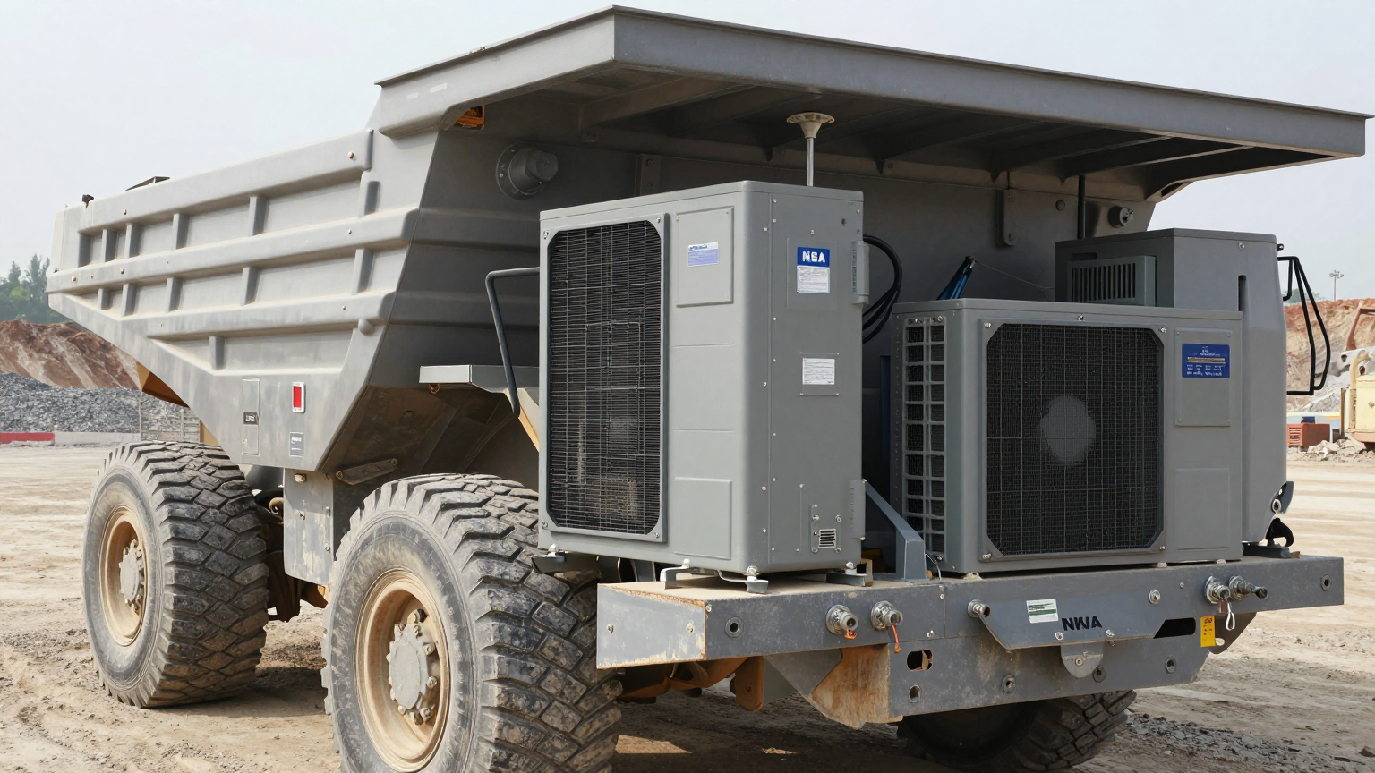
In the world of industrial and mobile equipment, thermal management is a battle fought on two fronts. First, you must remove the heat generated by critical electronics. Second, you must ensure the cooling system itself can survive the harsh physical environment it occupies. An electronics enclosure on an autonomous mining haul truck, a guidance system on an AGV navigating a factory floor, or a control cabinet on a railcar all face a constant barrage of shock and vibration. When a cooling unit fails, it’s not just a component failure; it’s a mission failure that can lead to catastrophic downtime, costly field repairs, and the derating or destruction of the very electronics it was meant to protect. The stakes are simply too high for a “bolt it on and hope for the best” approach.
By the end of this article, you will be able to confidently decide on a robust mounting strategy for a compact air conditioner that accounts for the specific shock and vibration profile of your application. In this analysis, we prioritize mechanical survivability and thermal uptime over minimizing footprint, because a failed cooling unit offers zero value, regardless of its size or efficiency. We will explore the engineering principles of isolation, common failure modes, and a practical checklist for successful implementation.

Deployment Context: Where Rigid Mounting Fails
Theory is useful, but real-world examples highlight the consequences of underestimating dynamic forces. Here are two common scenarios where a simplistic mounting approach leads to premature failure.
Scenario A: Autonomous Guided Vehicles (AGVs) in Logistics
An engineering team deployed a fleet of AGVs in a large distribution center. To cool the primary navigation and control module, a compact DC air conditioner was rigidly bolted to the vehicle’s steel frame. Within six months, several AGVs began experiencing intermittent guidance failures, eventually traced to overheating. The investigation revealed that the constant, high-frequency vibration transmitted from the solid tires rolling over uneven concrete floors had caused fatigue fractures in the brazed copper refrigerant lines of the aircon units. The slow leak of refrigerant eventually rendered the cooling systems useless, demonstrating that even seemingly low-level, persistent vibration is a potent source of failure.
Scenario B: Rail-Side Communications Cabinet
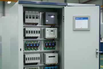
A system integrator installed a series of sealed NEMA enclosures along a railway to house signal amplifiers and backup power systems. Each cabinet was fitted with a small air conditioner to combat solar load and internal heat. The cabinets were mounted to poles that were subject to significant, intermittent shock and low-frequency vibration every time a train passed. The rigidly mounted cooling units began failing in under a year. The primary failure mode was brinelling of the condenser fan motor bearings, caused by the repetitive impact loads. This led to seized fans, which in turn caused the compressor to overheat and trip on its thermal overload, resulting in unreliable communications.
Common Failure Modes & System Constraints
Understanding how and why these systems fail is the first step toward designing a resilient solution. The following list, ordered by likelihood, details the symptoms and root causes of failures in high-vibration environments.
- Symptom: Gradual Loss of Cooling → Cause: Refrigerant leak from fatigue fracture at brazed joints or compressor connections. → Why it matters: This leads to a total, unrecoverable loss of cooling capacity and requires expensive field replacement.
- Symptom: Intermittent System Shutdowns → Cause: Solder joints on the PCB crack, or electrical connectors work themselves loose from constant vibration. → Why it matters: Operation becomes unreliable, potentially corrupting data or causing unpredictable behavior in the host equipment.
- Symptom: Excessive Noise or Rattling → Cause: Fasteners loosen, or the fan assembly becomes imbalanced after a shock event. → Why it matters: This is a clear acoustic indicator of impending mechanical failure and can violate operational noise specifications.
- Symptom: Reduced Airflow and High Head Pressure → Cause: Premature failure of fan motor bearings due to shock-induced brinelling or wear. → Why it matters: The system can no longer reject heat effectively, leading to reduced cooling capacity and severe strain on the compressor.
- Symptom: Catastrophic Compressor Seizure → Cause: Internal mechanical damage or lubrication failure within the compressor from extreme, repetitive g-forces. → Why it matters: This is the most severe failure mode, requiring a complete unit replacement.
- Symptom: Water or Dust Ingress → Cause: The housing or mounting flange of the cooling unit cracks due to stress concentrations at rigid mounting points. → Why it matters: The environmental seal is compromised, exposing internal electronics to contaminants and corrosion.
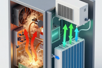
Engineering Fundamentals: Isolation, Not Rigidity
The core principle of designing for dynamic environments is often counterintuitive. The goal is not to make the mounting as stiff and strong as possible. Instead, the goal is to isolate the sensitive equipment from the source of the vibration. A rigid connection is a highly efficient conductor of vibrational energy, particularly at high frequencies, which are most damaging to electronics and brazed joints.
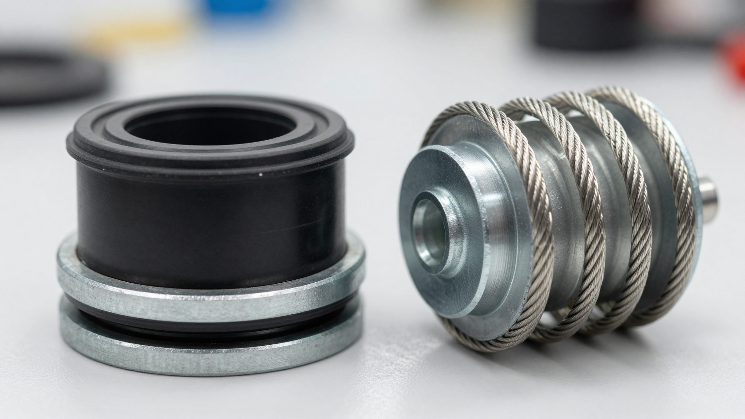
Think of the cooling unit and its mounting as a spring-mass-damper system. Every system has a natural frequency at which it prefers to vibrate. If the frequency of the vibration from the environment (the “forcing frequency”) matches the natural frequency of the mounted unit, resonance occurs. This dramatically amplifies the motion and stress within the unit, guaranteeing a rapid failure. The engineering task is to select an interface—typically elastomeric mounts or wire rope isolators—that shifts the system’s natural frequency far away from the dominant forcing frequencies of the environment.
A common misconception is that a thick steel mounting plate and oversized bolts create a robust installation. In reality, this approach creates a mechanically “short circuit”. It ensures that nearly 100% of the shock and vibration energy from the chassis is transmitted directly into the cooling unit. A correctly engineered solution uses isolators to act as a mechanical low-pass filter, absorbing and dissipating the energy before it can cause damage. This is the fundamental difference between simply attaching a unit and truly integrating it.
Key Specifications for High-Vibration Applications
When evaluating a Micro DC Aircon for a mobile or rugged application, thermal performance is only half the story. You must demand mechanical performance data from the manufacturer or be prepared to perform qualification testing. A simple spec sheet is not enough. Here are the go/no-go specifications you must confirm:
- Vibration Profile: Does the manufacturer provide data on the unit’s survivability under random vibration? This is typically specified as a Power Spectral Density (PSD) profile in G² per Hertz across a frequency range (e.g., 20-2000 Hz). This is far more realistic than a simple sinusoidal sweep.
- Shock Profile: What is the maximum g-force the unit can withstand? This should be defined by peak acceleration, duration, and waveform (e.g., 20 G, 11 ms, half-sine). This is critical for equipment that may be dropped or subject to sudden impacts.
- Axis of Operation: Have the tests been performed on all three axes (X, Y, and Z)? Vibration and shock are rarely confined to a single direction in the real world.
- Operational vs. Survival: Is the unit rated to operate normally during vibration, or only to survive it while powered off? For most applications, operational performance is a must.
- Relevant Standards: Has the unit been tested according to recognized standards? Look for references to MIL-STD-810 (for defense), RTCA DO-160 (for aerospace), or specific SAE (automotive) or EN (rail) standards relevant to your industry.
- Compressor Design: The heart of the system is the compressor. A miniature BLDC rotary compressor is inherently more balanced and resilient to vibration than a traditional reciprocating piston design, providing a better foundation for a rugged system.

Engineering Selection Matrix: Logic Gates for Integration
Moving from theory to practice requires a structured decision-making process. Use these logic gates to guide your mechanical integration design.
Logic Gate 1: Characterize the Environment
- The Constraint Gate: Is the operational environment static (e.g., a fixed control room) or dynamic (e.g., mounted on a vehicle, portable equipment, or vibrating machinery)?
- The Decision Trigger: If the equipment is mobile, subject to transport shock, or mounted near significant vibration sources like engines or pumps, you must proceed with an isolation strategy.
- Engineering Resolution: The default design path shifts from rigid mounting to one based on engineered vibration isolators. This decision should be made at the earliest stage of mechanical design.
- Integration Trade-off: This adds the cost of isolators and engineering analysis, and it requires defining a “sway space” around the unit. However, it is the only way to ensure long-term reliability.
Logic Gate 2: Select the Isolation Method
- The Constraint Gate: Is the primary threat high-frequency, low-amplitude vibration (e.g., engine hum) or low-frequency, high-impact shock (e.g., potholes, drops)?
- The Decision Trigger: Use an accelerometer to measure the actual vibration profile at the intended mounting location. If the profile is dominated by frequencies above 50 Hz, elastomeric (rubber) mounts are often a good fit. If severe, multi-axis shock is the main concern, wire rope isolators offer superior performance.
- Engineering Resolution: Work with an isolation specialist or use manufacturer software to select an isolator that places the mounted system’s natural frequency well below the lowest significant forcing frequency. A common rule of thumb is a separation of at least 40% (e.g., for a 30 Hz vibration source, the system’s natural frequency should be below ~18-20 Hz).
- Integration Trade-off: Elastomeric mounts are cost-effective and compact but can be sensitive to temperature and fluid exposure. Wire rope isolators are extremely durable and handle a wide temperature range but are bulkier and more expensive.
Logic Gate 3: Design the Supporting Interfaces
- The Constraint Gate: How do you maintain sealed airflow and electrical connections to a unit that is designed to move relative to the enclosure?
- The Decision Trigger: As soon as an isolation system is chosen, all rigid connections to the unit become potential failure points and vibration short circuits.
- Engineering Resolution: For airflow, use flexible, high-quality silicone or neoprene boots or bellows to connect the air conditioner’s condenser and evaporator ports to the enclosure walls. For electrical connections, provide generous service loops in all wiring to allow for movement without putting stress on the cables or connectors. As an example, a unit like the DV1920E-AC (Pro) requires both power and potential control signal connections, all of which need this slack.
- Integration Trade-off: This increases the complexity of the enclosure’s sheet metal design and requires sourcing additional components. However, it is non-negotiable for maintaining both the environmental seal and the effectiveness of the isolation system.
Implementation & Verification Checklist
A successful design requires meticulous installation and verification. Follow this checklist to ensure your mounting system performs as intended.
-
Mechanical Installation
- Mounting Surface: Confirm the surface is flat and rigid. A flimsy panel will defeat the purpose of the isolators. Add stiffening ribs if necessary.
- Isolator Orientation & Loading: Install isolators in the correct orientation. Ensure the unit’s weight is evenly distributed among all isolators to match their specified load rating.
- Fastener Security: Use self-locking nuts (e.g., Nyloc) or a medium-strength thread-locking compound on all fasteners. Torque bolts to the manufacturer’s specification.
- Sway Space Clearance: Manually deflect the unit to its maximum expected travel in all directions. Verify that it does not impact any adjacent components, walls, or cable bundles.
-
Electrical Connections
- Service Loops: Create smooth, gentle curves in all wiring connected to the isolated unit. Avoid sharp bends or tight zip ties that restrict movement.
- Strain Relief: Securely clamp all cables to the non-moving chassis or enclosure wall, a few inches away from the connection point on the unit. The strain relief should anchor the cable, not the service loop.
-
Thermal & Airflow Integrity
- Flexible Ducting: Ensure any flexible air ducts are properly sealed with clamps and are not kinked or compressed, which would restrict airflow.
- Condensate Drain: If applicable, the condensate drain line must also be flexible and routed with a downward slope, free of kinks or loops that could trap water.
-
Post-Installation Verification
- Operational Test: Power on the system and listen for any unusual noises. A properly isolated system should run more quietly than a hard-mounted one.
- Vibration Measurement (Recommended): For critical applications, place one accelerometer on the chassis and another on the body of the air conditioner. With the equipment running, confirm that the vibration amplitude on the air conditioner is significantly lower than on the chassis. This is the ultimate proof that your isolation is working.
Frequently Asked Questions (FAQ)
Should I use soft or stiff vibration mounts?
This depends entirely on the weight of the unit and the frequency of the vibration. A “soft” mount (low durometer elastomer or low spring rate) is needed to isolate low frequencies, but it must still be stiff enough to support the unit’s weight without excessive sagging. The key is to choose a mount based on its load-deflection curve and natural frequency characteristics, not just a generic sense of hardness.
What if my enclosure needs to be sealed to an IP or NEMA rating?
Sealing is absolutely achievable. The seal is made between the cooling unit’s mounting flange and the enclosure wall. The vibration isolators are typically installed between the unit’s flange and the wall. A continuous, high-quality gasket on the flange is essential. Any flexible ducts for airflow must also be sealed to the enclosure wall with their own gaskets or sealant.
Will vibration isolation cause issues with condensate drainage?
No, as long as it’s managed correctly. The condensate drain port on the unit must be connected to a flexible tube. This tube should be given a service loop just like the electrical wiring and must maintain a continuous downward slope to the final drain point to prevent water from being trapped.
What is the first thing I must measure before designing the mounting system?
You must measure the vibration profile at the exact location where the cooling unit will be installed, while the host equipment is operating in its most severe, real-world condition. A 3-axis accelerometer and a data logger are the correct tools for this job. Designing without this data is guesswork.
How do I validate that the installation is providing effective micro dc aircon vibration resistance?
The most definitive method is to take before-and-after measurements. Measure the vibration on the chassis and on a rigidly bolted test plate. Then, install the unit with the selected isolators and measure again. A successful design will show a dramatic reduction (often 80-95%) in the vibration transmitted to the air conditioner at the target frequencies.
Can’t I just bolt the Micro DC Aircon directly to a thick, heavy plate?
While this adds mass, it does not provide isolation. It may shift the resonant frequency slightly, but it still creates a rigid path for vibrational energy to travel. For any mobile or dynamic application, this is an unreliable approach that will likely lead to the failure modes discussed earlier.
Conclusion: Design for the Real World
Effective shock resistant enclosure cooling is about more than just thermal calculations; it’s about holistic system integration. For any application outside of a stationary, climate-controlled room, assuming the mechanical environment is benign is a critical design flaw. By prioritizing a proper isolation strategy over simple rigid mounting, you are not adding unnecessary complexity—you are designing for reliability and ensuring the uptime of the entire system.
The best-fit approach is always one that is informed by data. Measure your environment, understand the principles of isolation, and select components that shift the system’s natural frequency away from the sources of vibration. This methodology transforms the cooling unit from a potential point of failure into a resilient, long-lasting asset. If your project involves challenging shock and vibration profiles, our engineering team can help analyze your requirements and recommend a suitable thermal unit and integration strategy. Contact us to discuss your specific enclosure geometry, power constraints, and environmental demands for achieving true micro dc aircon vibration resistance.
0 条评论