The Silent Killers of Harsh Environment Electronics
In the controlled sterility of a laboratory, an industrial controller might run indefinitely. But in the field—bolted to a vibrating mining rig in the Pilbara or enclosed in a roadside cabinet buffering coastal winds—the operational reality changes drastically. For OEM engineers and system integrators, the challenge is rarely the logic of the circuit itself; it is the survival of that circuit against the physical assault of its surroundings. Harsh environment electronics do not fail because the code was wrong; they fail because the physical barrier between the delicate silicon and the chaotic world collapsed.
When a system goes dark in a remote location, the cost is not merely the replacement hardware. It is the truck roll, the specialized technician’s travel time, the halted production line, and the data gap that can never be filled. The forensic path to these failures almost always leads back to one of four physical stressors: thermal runaway, particulate ingress (dust), moisture-induced corrosion, or mechanical fatigue from vibration. Often, it is a synergistic combination of these factors.
This engineering guide analyzes the specific failure mechanisms driven by dust, moisture, and vibration in electronics. We will examine why traditional filtration methods often accelerate failure in remote deployments and how active, closed-loop thermal management—specifically using Micro DC Aircon technology—provides the necessary isolation to ensure mean time between failures (MTBF) targets are met. By the end of this article, you will have a clearer framework for specifying cooling solutions that do not just lower temperature, but actively harden the system against environmental aggression.

Deployment Context: Where Theory Meets Reality
To understand the engineering requirements for harsh environment electronics, we must look at the specific boundary conditions of high-stakes deployments. These are not hypothetical scenarios; they are the daily operating environments for thousands of critical systems.
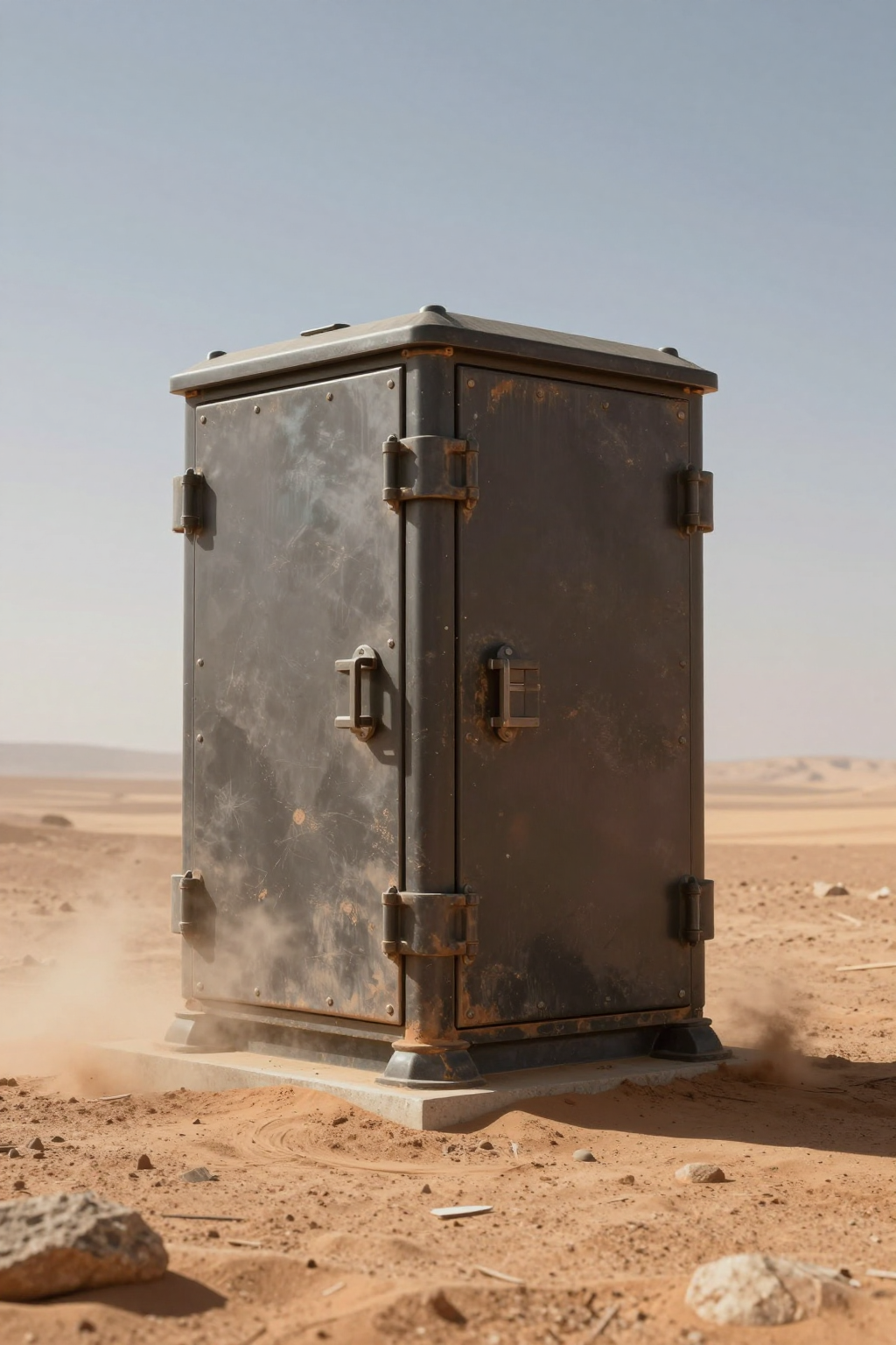
Scenario A: The Off-Grid Telecom Node
Consider a solar-powered repeater station in a high-desert environment. The ambient temperature fluctuates wildly, swinging from near-freezing at night to 45°C (113°F) by mid-afternoon. Solar loading on the enclosure adds another 15°C to 20°C to the internal air temperature. The air is dry, but laden with fine, abrasive silica dust. If the cooling strategy relies on ambient air intake (fans and filters), the filters will clog within weeks. Once clogged, airflow drops, internal temperatures spike, and the CPU throttles or shuts down. If the filters are removed to prevent clogging, the dust coats the PCB, insulating components and eventually causing short circuits if humidity rises even marginally.
Scenario B: The Mobile Medical Logistics Unit
In a mobile refrigeration unit transporting vaccines across tropical regions, the constraints shift. Here, humidity is the primary enemy. The ambient air is saturated. If the electronics enclosure “breathes” via passive vents, the daily thermal cycling causes pressure differentials that suck moist air into the cabinet. When the electronics cool down at night, that moisture condenses on the boards. Add the constant low-frequency vibration from the vehicle’s diesel engine and the road surface, and you have a recipe for solder joint fatigue accelerated by corrosion. A standard commercial cooling unit cannot survive the vibration; a standard fan cannot stop the moisture.
Technical Friction Points & Failure Modes
The enemies of uptime are persistent and microscopic. Understanding the mechanism of failure is the first step in designing a defense.
- Dust Ingress and Thermal Blanketing: Dust is rarely just “dirt.” In industrial settings, it can be conductive (carbon fiber dust), magnetic (iron filings), or hygroscopic (absorbing moisture). Even non-conductive dust poses a severe threat. As it settles on heatsinks and ICs, it forms an insulating layer that increases thermal resistance ($R_{th}$). A fan might be spinning at full RPM, but if the heatsink is coated in dust, the heat cannot transfer to the air. The component overheats despite active airflow.
- Moisture and Electrochemical Migration: Harsh environment electronics are particularly susceptible to dew point crossings. When warm, humid air enters an enclosure and contacts a surface below the dew point, condensation forms. Water alone is bad, but water mixed with dust creates a conductive sludge. This leads to dendritic growth—metal ions migrating between traces under voltage bias—eventually causing a hard short.
- Vibration-Induced Fatigue: Mobile applications introduce a spectrum of vibration frequencies. Heavy components like capacitors, inductors, and cooling compressors act as sprung masses. If the mounting system does not dampen these frequencies, or if the resonant frequency of the cooling system matches the vehicle’s engine, mechanical fatigue sets in. Solder joints crack, and rigid refrigerant piping can fracture, leading to a loss of cooling charge.
- Power Instability: Remote sites often rely on battery banks, solar arrays, or generators. Voltage can fluctuate significantly. A cooling system designed for a stable 110VAC grid connection requires a bulky, inefficient inverter to run on DC power, introducing another point of failure. Native DC components are essential for efficiency and reliability.
Engineering Fundamentals: The Logic of Closed-Loop Cooling
The fundamental flaw in many cooling designs for harsh environment electronics is the reliance on ambient air exchange. Fans and filters operate on the assumption that the outside air is clean enough and cool enough to directly contact the electronics. In harsh environments, this assumption is false.
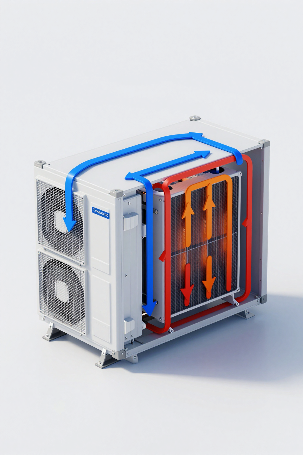
The engineering solution is closed-loop cooling. In this architecture, the air inside the enclosure never mixes with the outside air. The enclosure is sealed (aiming for NEMA 4 or IP65 standards). The cooling system—typically a vapor-compression cycle—recirculates the internal air, removing heat via a heat exchanger (evaporator) and rejecting it to the outside via a separate path (condenser).
Why Vapor Compression?
While thermoelectric (Peltier) coolers are solid-state, they often lack the coefficient of performance (COP) required for high-heat-load applications, consuming too much power for solar/battery setups. Vapor compression systems, specifically those utilizing Micro DC Aircon technology, offer a much higher COP. They use a refrigerant phase change to absorb heat efficiently.
Crucially, a Micro DC Aircon actively dehumidifies the internal air. As air passes over the cold evaporator coil, moisture condenses on the coil (not the electronics) and is drained away. This keeps the internal environment dry, mitigating the risk of corrosion even if the outside humidity is 95%.
Performance Data & Verified Specs
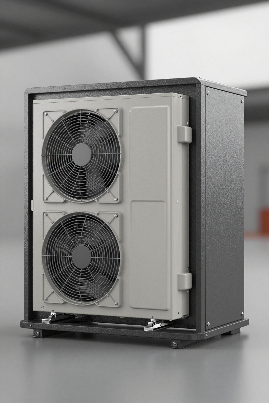
For engineers specifying cooling for mobile or off-grid systems, the physical size and power consumption of the cooling unit are as critical as its cooling capacity. The Arctic-tek Micro DC Aircon series utilizes miniature BLDC inverter rotary compressors to achieve high power density.
The following table outlines verified specifications for the DV series, which are designed for direct integration into DC power buses (12V, 24V, 48V), eliminating the need for inverters.
| Model (Series Example) | Voltage (DC) | Nominal Cooling Capacity | Refrigerant | Compressor Type |
|---|---|---|---|---|
| DV1910E-AC (Pro) | 12V | 450W | R134a | BLDC Inverter Rotary |
| DV1920E-AC (Pro) | 24V | 450W | R134a | BLDC Inverter Rotary |
| DV3220E-AC (Pro) | 24V | 550W | R134a | BLDC Inverter Rotary |
| DV1930E-AC (Pro) | 48V | 450W | R134a | BLDC Inverter Rotary |
Note on Vibration Resistance: The core of these units is the miniature DC compressor (e.g., QX1902VDL). Rotary compressors are inherently more balanced than reciprocating types, reducing vibration transmission. Furthermore, the compact mass of these compressors allows for more robust mounting solutions that can withstand the g-forces typical of mobile applications.
Field Implementation Checklist
Designing for dust moisture vibration electronics protection requires a holistic approach. It is not enough to just bolt on an air conditioner; the entire enclosure ecosystem must be considered. Use this checklist during your design review:
- Mechanical Integrity & Sealing
- Gasket Selection: Ensure door gaskets are continuous and rated for the temperature extremes. A cooling unit cannot hold a temperature if the door seal leaks.
- Cable Entry: Use rated cable glands (IP68 preferred) for all penetrations. Do not leave open holes for wiring, as these bypass the closed-loop logic.
- Mounting Rigidity: Ensure the enclosure wall is stiff enough to support the weight of the cooling unit without flexing, which could compromise the seal during vibration.
- Electrical Architecture
- Voltage Matching: Select a cooling unit that matches your primary DC bus (e.g., 48V for telecom, 24V for trucking). Avoid DC-AC-DC conversions.
- Over-Current Protection: Size fuses/breakers for the startup current, although BLDC inverter drivers typically feature soft-start capabilities to mitigate inrush spikes.
- Thermal Management Strategy
- Airflow Path: Verify that the internal airflow from the cooling unit is not blocked by tall components or cable bundles. Cold air must reach the hot spots.
- Sensor Placement: If using an external temperature probe for control, place it at the return air inlet of the cooling unit, not directly on a heatsink, to get an accurate average enclosure temperature.
- Maintenance & Lifecycle
- Filter Access: Even closed-loop systems have an external condenser fan. Ensure the external filter (if present) is accessible for cleaning without opening the sealed electronics compartment.
- Drainage: Ensure the condensate drain tube is routed correctly out of the enclosure and includes a trap or valve to prevent insect/dust ingress back up the tube.
Expert Field FAQ
Q: Can I run a Micro DC Aircon directly from a solar panel?
No. While the voltage might match, solar panels act as current sources with fluctuating output. You must buffer the power through a battery bank or a stable DC power supply. The compressor requires a stable voltage source to operate the inverter drive correctly.
Q: How does the system handle high ambient temperatures, such as 50°C?
Standard refrigerant cycles have limits, but specific models (like those using the QX1902VDL-T tropical compressor) are optimized for high compression ratios required in high ambient conditions. Always check the derating curve. Capacity drops as ambient temperature rises; ensure you have a safety margin in your sizing.
Q: What is the advantage of R134a vs. R290 in these small units?
R134a is the industry standard for stability and safety (non-flammable). R290 (propane) offers excellent thermodynamic properties and low Global Warming Potential (GWP), but requires stricter safety handling due to flammability. For sealed, low-charge micro systems, R290 is becoming increasingly viable and efficient.
Q: Will the vibration from the compressor damage my sensitive sensors?
Micro DC Aircon units use rotary compressors which have much lower vibration signatures than reciprocating compressors. However, for extremely sensitive optical or MEMS sensors, we recommend using vibration isolation mounts for the cooling unit itself or isolating the sensor sub-assembly within the enclosure.
Q: What happens if the battery voltage drops?
The integrated driver board (PCB) on the DV series includes under-voltage protection. If the voltage drops below a set threshold (e.g., to protect the battery from deep discharge), the compressor will shut down safely and restart automatically once the voltage recovers.
Q: Can I mount the unit horizontally?
Generally, vapor compression systems must be mounted within a few degrees of vertical to ensure proper oil return to the compressor. However, specific custom configurations or Micro Liquid Chiller (KVB150Z) setups may offer more packaging flexibility. Consult the spec sheet for the specific model’s allowable tilt angles.
Conclusion & System Logic
The decision to deploy electronics in harsh environments is a decision to fight physics. Heat wants to degrade your silicon; dust wants to insulate it; moisture wants to short it; vibration wants to break it. Passive cooling strategies—vents, fans, and oversized heatsinks—are often insufficient because they invite the enemy inside the gates.
For mission-critical uptime, the logic points toward isolation. By sealing the enclosure and employing active, closed-loop thermal management like the Micro DC Aircon series, you decouple the internal electronics from the external chaos. You create a micro-climate where your components can operate as if they were in a server room, regardless of whether they are actually in the Mojave Desert or on a North Sea oil rig.
When specifying your next system, look beyond the nominal cooling watts. Consider the voltage architecture, the refrigerant safety, and the mechanical robustness of the compressor. If you are navigating the trade-offs between size, power, and cooling capacity for a specific harsh environment project, contact the Arctic-tek engineering team. We can help you match the thermal load to the right Micro DC solution to ensure your system survives the field.


0 条评论