Defining the Closed-Loop Cooling Meaning: A Forensic Approach to Enclosure Failure
The most expensive silence in an industrial setting is the silence of a system that has shut down due to thermal failure. For OEM engineers and system integrators, the post-mortem of a failed electronics enclosure often reveals a common culprit: the environment itself. When we analyze the debris inside a compromised cabinet—conductive dust on a PCB, corrosion on a busbar, or moisture pooling at the bottom of a drive—the root cause is rarely the electronics. It is the cooling strategy.
This brings us to a critical engineering definition: the closed-loop cooling meaning. In the context of industrial enclosures, a closed-loop system is defined by the complete isolation of the internal cabinet atmosphere from the external ambient environment. Unlike open-loop systems (fans and filter kits) that continuously pull outside air into the enclosure, a closed-loop system recirculates the same internal air, removing heat through a heat exchanger or active refrigeration cycle without ever allowing outside contaminants to enter.
Understanding the strict closed-loop cooling meaning is the first step in designing resilient systems for harsh environments. It is not merely about temperature reduction; it is about environmental isolation. By severing the link between the sensitive electronics and the hostile outside world, engineers can guarantee uptime in locations where ambient air is effectively a weapon.

Deployment Context: The High Stakes of Contamination
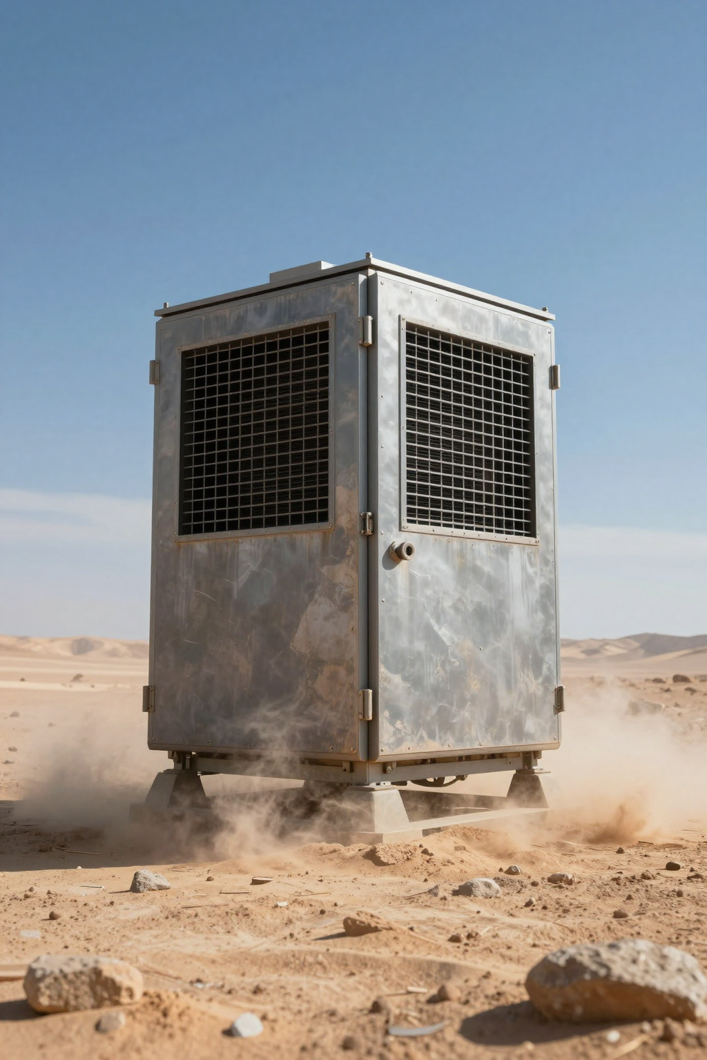
To understand why isolation is non-negotiable, we must look at where these systems live. Consider a remote telecom base station powered by solar arrays in the Nevada desert. The ambient temperature fluctuates wildly, reaching peaks that exceed the safe operating limits of lithium-ion batteries and rectifiers. However, heat is only half the battle. The fine silica dust in this region is pervasive. If an open-loop fan system is used, the filters will clog within weeks, reducing airflow to near zero and causing a thermal runaway event. If the filters are removed to improve airflow, the dust coats the electronics, creating insulating blankets that trap heat at the component level or, worse, bridging circuits when humidity rises at night.
Alternatively, consider a coastal sensor node monitoring maritime traffic. Here, the enemy is salt fog. Even a small amount of saline air drawn into the enclosure initiates rapid corrosion of contacts and solder joints. In these scenarios, the closed-loop cooling meaning translates directly to asset survival. The enclosure must act as a vault, not a sieve.
Technical Friction Points: The “Unseen Enemies” of Open Loops
When an integrator defaults to open-loop cooling (fans) to save on upfront costs, they introduce several technical friction points that inevitably lead to higher operational expenditures (OPEX) and reliability debts.
- Filter Maintenance Fatigue: In high-dust environments, filters require cleaning or replacement at intervals that are often logistically impossible for remote sites. A clogged filter turns a cooling fan into a passive obstruction, causing internal temperatures to spike above ambient.
- Humidity Equalization: Open-loop systems cannot control humidity. If the outside air is humid, the inside air is humid. When temperatures drop (dew point crossover), condensation forms on internal components. Closed-loop systems, particularly active compressor-based units, actively dehumidify the internal air.
- Thermal Saturation: Fans can only cool an enclosure to slightly above the ambient temperature. If the ambient air is 45°C and the electronics are rated for 40°C, an open-loop system is physically incapable of protecting the equipment, regardless of airflow volume. This is a thermodynamic hard limit.
- Contaminant Ingress: Even with high-quality filters, microscopic particles and corrosive gases pass through. Over time, these accumulate to cause short circuits or thermal throttling.
Engineering Fundamentals: The Physics of Isolation
The engineering logic behind closed-loop cooling relies on separating the “evaporator” (internal) air path from the “condenser” (external) air path. In a Micro DC Aircon, this separation is physical and absolute.
The Thermal Barrier
Heat must be moved from the inside to the outside without moving the air itself. This is achieved through a vapor-compression cycle. Inside the enclosure, a fan circulates the trapped air through a cold evaporator coil. The refrigerant inside the coil absorbs the heat, boiling from a liquid to a gas. This heat-laden gas is then pumped by a BLDC inverter rotary compressor to the external condenser coil.
Rejection vs. Exchange
At the external side, a separate fan blows ambient air through the hot condenser coil. The heat transfers from the refrigerant to the ambient air, but the ambient air never touches the internal components. The refrigerant condenses back to a liquid and returns to the evaporator to repeat the cycle. This mechanism explains the core of the closed-loop cooling meaning: energy crosses the barrier, but matter (air, dust, moisture) does not.
Active vs. Passive Closed-Loop
It is important to distinguish between passive closed-loop (heat exchangers) and active closed-loop (air conditioners). A heat exchanger relies on the temperature difference between inside and outside. It can only cool the enclosure if the outside is colder than the inside. An active system, like a Micro DC Aircon, uses a compressor to pump heat “uphill,” allowing the enclosure to remain at 25°C even when the outside is 50°C. For most critical electronics in harsh climates, active cooling is the only viable option.
Performance Data & Verified Specs
When selecting a closed-loop solution, engineers must match the cooling capacity to the heat load and the available power bus. Arctic-tek’s Micro DC Aircon series utilizes miniature DC compressors to provide high cooling density in a compact footprint, integrating directly with 12V, 24V, or 48V DC battery banks common in off-grid and mobile applications.
| Model (Example) | Voltage (DC) | Nominal Cooling Capacity | Refrigerant | Compressor Type |
|---|---|---|---|---|
| DV1910E-AC (Pro) | 12V | 450W | R134a | BLDC Inverter Rotary |
| DV1920E-AC (Pro) | 24V | 450W | R134a | BLDC Inverter Rotary |
| DV1930E-AC (Pro) | 48V | 450W | R134a | BLDC Inverter Rotary |
| DV3220E-AC (Pro) | 24V | 550W | R134a | BLDC Inverter Rotary |
Note: Cooling capacity varies by model and ambient conditions. The series supports variable-speed operation via the integrated driver board, allowing the system to throttle performance based on thermal demand.
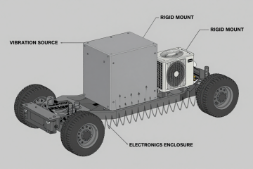
Field Implementation Checklist: Securing the Loop
Implementing a closed-loop system requires more than just bolting an air conditioner to a cabinet. The integrity of the “loop” is defined by the quality of the enclosure sealing. Here are the best practices from the field:
Mechanical Integrity
- Gasket Compression: Ensure the mounting gasket of the cooling unit is compressed evenly. A gap of even one millimeter compromises the IP rating and invalidates the closed-loop cooling meaning.
- Cable Entry Sealing: Use rated cable glands (PG or NEMA rated) for all penetrations. Do not use simple rubber grommets that can dry rot or deform. Expanding foam is not a permanent seal.
- Door Alignment: Check that the enclosure door does not warp under the weight of the cooling unit. Reinforce the door if necessary to maintain a tight seal against the frame.
Thermal Management
- Airflow Short-Cycling: Ensure the cold air discharge from the cooling unit is not immediately sucked back into the return intake. Use baffles or ducting if the cabinet is densely packed.
- Hot Spot Targeting: Position the cooling unit so the cold air stream hits the hottest components (e.g., VFDs or rectifiers) first.
Electrical Integration
- Voltage Drop: For DC systems, ensure the cabling from the battery to the cooling unit is sized correctly to prevent voltage drop during compressor startup, even though BLDC motors have soft-start capabilities.
- Low Voltage Disconnect: Configure the controller to shut down cooling before the battery is drained to a critical level, prioritizing the survival of the battery bank over the temperature of the enclosure if necessary.
Expert Field FAQ
Q: Does “closed-loop” mean the enclosure is airtight?
A: Not necessarily “hermetic” like a spacecraft, but it must be sealed to NEMA 4/4X or IP55/IP65 standards. Small pressure equalization vents (e.g., Gore vents) are often used to prevent pressure buildup from temperature changes while blocking moisture.
Q: Can I use a closed-loop system on a vented cabinet?
A: No. If the cabinet has louvers or vents, you must seal them with cover plates. Running an air conditioner on a vented cabinet is like running your home AC with the windows open—it will never reach the setpoint and will cause condensation issues.
Q: How does closed-loop cooling handle condensation?
A: Active closed-loop systems (air conditioners) naturally dehumidify the air as it passes over the cold evaporator coil. This water is collected and typically drained outside the enclosure. This is a major benefit over heat exchangers, which do not remove moisture.
Q: What is the difference between the closed-loop cooling meaning for liquid chillers vs. air conditioners?
A: The concept is the same—isolation. In a Micro Liquid Chiller (like the KVB150Z), the coolant loop is closed, and the heat is rejected via a radiator. In an air conditioner, the air volume is the closed loop. Both prevent external contamination.
Q: Why choose DC voltage for closed-loop cooling?
A: Using DC (12V/24V/48V) allows the cooling system to run directly off the battery bank. This ensures that cooling continues during a power outage, which is critical for telecom and safety systems. AC-powered units would require a large inverter, introducing efficiency losses.
Q: Is a filter fan ever “closed-loop”?
A: No. By definition, a fan that pulls outside air in is an open-loop system. Adding a finer filter does not change the loop topology; it only changes the size of particles allowed in.

Conclusion & System Logic
The decision to move from open-loop to closed-loop cooling is often a decision to prioritize long-term reliability over short-term savings. While fans are cheap, the cost of replacing a corroded drive or a dust-choked server far outweighs the investment in a proper thermal management system. The closed-loop cooling meaning is ultimately about control—controlling the temperature, controlling the humidity, and controlling the cleanliness of the environment in which your critical electronics operate.
For systems deployed in harsh, mobile, or remote environments, relying on ambient air is a gamble that rarely pays off. By utilizing active, DC-powered closed-loop solutions like the Micro DC Aircon series, engineers can ensure that their equipment operates in a clean, cool “cleanroom” environment, regardless of whether it is sitting in a desert, a factory floor, or a marine terminal. When the environment is the enemy, isolation is the only defense.
0 条评论