Angle Lock: The critical decision is selecting a thermal management strategy that guarantees temperature uniformity, not just bulk heat removal. The primary failure modes are localized hot spots causing premature component failure and condensation-induced shorts. The dominant constraint is maintaining a sealed enclosure, protecting sensitive electronics from environmental hazards like dust and moisture.
Why Temperature Uniformity in a Sealed Cabinet is Non-Negotiable
In industrial automation, telecommunications, and outdoor digital signage, the failure of a single electronic component can trigger cascading system shutdowns, leading to costly downtime and emergency field service. Often, the root cause isn’t a faulty component but a flawed thermal management strategy. While engineers focus on total heat load, they can overlook a more insidious threat: thermal gradients. A sealed cabinet that is cool on average can still harbor destructive hot spots, leading to uneven component aging and unpredictable failures. The difference between a system that runs for ten years and one that fails in two often comes down to achieving consistent temperature uniformity in a sealed cabinet.
This article provides a data-driven framework for selecting the right cooling technology to prevent thermal imbalances. By the end, you will be able to determine the precise point at which passive cooling becomes insufficient and a closed-loop, active air conditioning system becomes essential. We will prioritize reliability and predictable component lifespan over simplistic, low-cost solutions that create long-term risk.
Deployment Context: Where Thermal Gradients Emerge
Theoretical calculations can miss the harsh realities of field deployment. Here are two common scenarios where non-uniform temperatures create significant reliability risks.
Scenario A: Roadside Telecom Cabinet
A network provider deployed a series of 4G/5G base station cabinets in a desert region. The cabinets were sealed to protect against sand and occasional rain. The initial design used a large heat exchanger, assuming it could handle the 300W internal load. However, intense solar loading on the cabinet’s south-facing side created an external surface temperature far exceeding the ambient air temperature. The heat exchanger couldn’t create a sufficient temperature differential, causing the internal temperature near the power amplifiers to spike, leading to signal degradation and intermittent resets during the hottest part of the day.
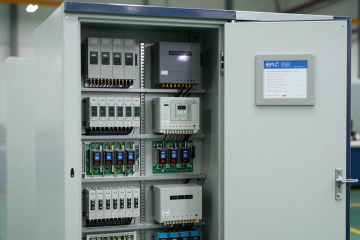
Scenario B: Factory Floor Control Panel
An automated welding line in a manufacturing plant uses a sealed NEMA-rated control panel located near the production machinery. The panel is exposed to high ambient temperatures and airborne metallic dust. The system integrator installed a thermoelectric (Peltier) cooler to protect the PLCs and VFDs inside. While the cooler kept the average temperature within limits, poor internal air circulation created a hot zone around the VFD at the top of the enclosure. This led to the premature failure of its capacitors, halting the entire production line for an emergency repair that cost thousands in lost productivity.
Failure Modes & Constraints Driven by Poor Uniformity
Thermal imbalances manifest as specific, preventable failures. Understanding these symptoms and their causes is the first step toward a robust design.
- Symptom: Premature capacitor failure → Cause: Localized heat above the component’s rating → Why it matters: Leads to power supply failure and unplanned system downtime.
- Symptom: Processor or FPGA throttling → Cause: Hot spot at the chip level due to stagnant air → Why it matters: Degrades system performance, causes data errors, and can corrupt processes.
- Symptom: Cable insulation embrittlement → Cause: Persistent high temperatures in a section of the cabinet → Why it matters: Increases risk of short circuits and electrical fires over the system’s lifespan.
- Symptom: Inaccurate sensor readings → Cause: Measurement drift from sensors operating outside their calibrated temperature range → Why it matters: Compromises process control and system safety.
- Symptom: Condensation on components → Cause: A cooling system that drops the component surface temperature below the dew point → Why it matters: Creates a high risk of short circuits and corrosion, especially in humid environments.
- Symptom: Gasket and seal degradation → Cause: Uneven thermal expansion and contraction of the cabinet enclosure → Why it matters: Compromises the NEMA/IP rating, allowing contaminants to enter.
- Symptom: Unpredictable system resets → Cause: Multiple components simultaneously operating at their thermal limits → Why it matters: These “ghost” failures are difficult to diagnose, eroding confidence in the system.
Engineering Fundamentals: The Closed-Loop Air Path
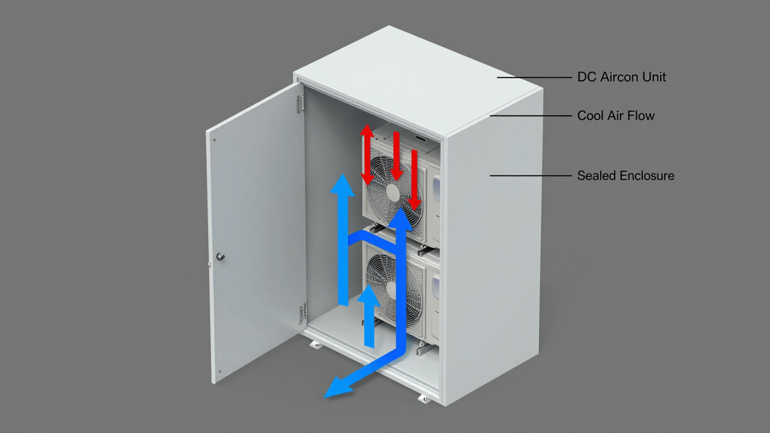
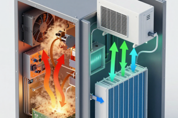
The key to achieving temperature uniformity in a sealed cabinet is establishing a predictable, closed-loop internal air path. In a sealed enclosure, you cannot simply vent hot air out; you must actively manage the internal environment. An active cooling system like a vapor-compression air conditioner does more than just remove heat—it creates continuous, forced-convection airflow.
This system pulls warm air from the top of the cabinet (where heat naturally stratifies), cools and dehumidifies it through an evaporator coil, and then pushes the cool, dry air back into the bottom of the cabinet. This creates a constant circulation pattern that churns the internal air, breaking up thermal layers and eliminating stagnant hot spots. The cool air is directed past the most critical heat-generating components first, ensuring they receive the most effective cooling before the air begins to warm on its path back to the evaporator inlet.
Common Misconception: A higher cooling capacity (BTU/hr or Watts) rating is always the best solution.
Correction: Raw cooling power is useless without effective air distribution. A massively oversized cooler that dumps cold air in one spot can be worse than a properly sized unit that ensures circulation. This can create extreme thermal gradients and condensation issues. The goal is not just to cool the cabinet, but to create a homogenous thermal environment where every component operates well within its specified temperature range. This is why the CFM (Cubic Feet per Minute) of the internal blower and the strategic placement of the cooling unit are as critical as the nominal cooling capacity.
Key Specifications for Active Cooling Systems
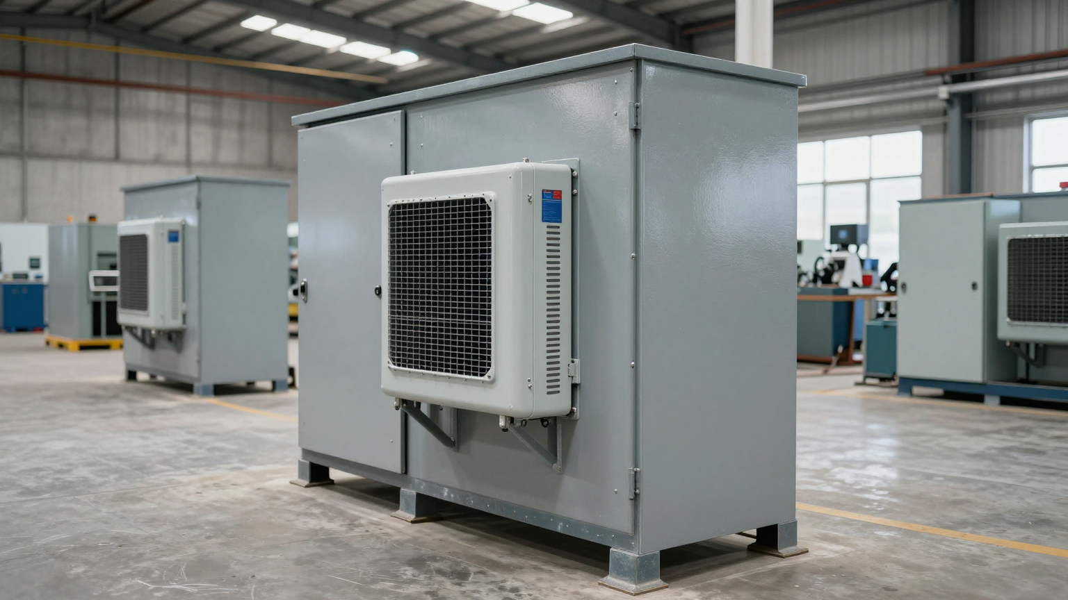
When evaluating an active cooling solution like a Micro DC Aircon, certain specifications are non-negotiable for ensuring performance and reliability. The table below outlines the typical parameter ranges for our series. When designing for temperature uniformity in a sealed cabinet, pay close attention to the cooling capacity relative to your heat load and the available DC voltage.
| Specification | Parameter Range / Type | Why It Matters for Uniformity |
|---|---|---|
| DC Voltage Options | 12V / 24V / 48V | Must match the existing DC power bus in the cabinet, avoiding the need for inefficient and heat-generating power converters. |
| Nominal Cooling Capacity | 100W – 900W | Must be sized to handle the total internal heat load plus any external solar or radiant load, with a safety margin. |
| Control System | Integrated PCB with inverter control | Variable-speed compressors and blowers allow the system to adapt to changing loads, maintaining a stable temperature instead of constant on/off cycling. |
| Refrigerant Type | R134a / R290 / R1234yf | Different refrigerants are optimized for different operating pressures and temperatures, impacting efficiency in various ambient conditions. |
| System Type | Vapor-Compression (BLDC Rotary) | Offers high efficiency (Coefficient of Performance), especially at large temperature differentials between internal and ambient air. |
Engineering Selection Matrix: Logic Gates for Thermal Design
Choosing the right cooling technology requires passing through a series of engineering logic gates. A failure at any gate invalidates the chosen solution and forces a move to a more robust technology.
Logic Gate 1: Ambient Temperature vs. Required Internal Temperature
- Constraint Gate: Can the internal electronics tolerate a temperature higher than the maximum external ambient temperature?
- Decision Trigger: If the maximum allowable internal temperature is at or below the maximum external ambient temperature, passive solutions (heat sinks, heat exchangers) and simple filtered fans are immediately disqualified. These methods can only dissipate heat to a level *above* the ambient temperature.
- Engineering Resolution: The system requires active, refrigerated cooling that can create a temperature differential (Delta T) where the inside is cooler than the outside. This mandates either a thermoelectric (Peltier) or vapor-compression (air conditioner) system.
- Integration Trade-off: Moving to active cooling introduces a power draw and requires a sealed enclosure, but it is the only way to guarantee operation in high-temperature environments.
Logic Gate 2: Sealed Enclosure Requirement
- Constraint Gate: Must the cabinet be sealed to protect against dust, moisture, salt fog, or other corrosive agents (e.g., NEMA 4/4X or IP66)?
- Decision Trigger: If the answer is yes, any solution that relies on exchanging air with the outside environment, such as filtered fan systems, is not viable. These systems inherently introduce contaminants and humidity.
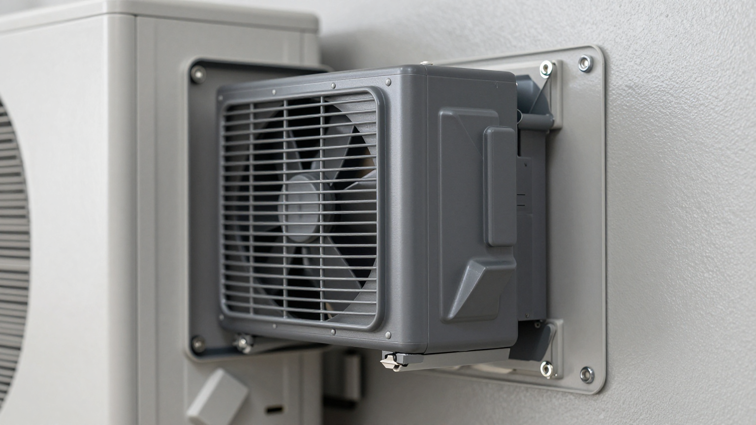
- Engineering Resolution: A closed-loop cooling system is required. Both thermoelectric coolers and compact DC air conditioners mount to the cabinet wall and circulate only the internal air, keeping the sealed integrity intact.
- Integration Trade-off: This increases the upfront cost compared to a fan and filter, but it is the only way to protect the electronics and ensure the warranty and reliability of the internal components.
Logic Gate 3: Cooling Power Density and Efficiency
- Constraint Gate: Is the total heat load high (e.g., > 200W) and/or is the required temperature differential large (e.g., > 15°C below ambient)?
- Decision Trigger: Thermoelectric coolers suffer from a steep drop-off in efficiency as the heat load and Delta T increase. For high-performance applications, a TEC unit would become excessively large, heavy, and power-hungry.
- Engineering Resolution: A vapor-compression system, such as a Micro DC Aircon, is the superior choice. Its Coefficient of Performance (COP) is significantly higher, meaning it removes more heat per watt of input power. This makes it ideal for handling heat loads from 200W to over 900W while maintaining a cool interior even in extreme heat.
- Integration Trade-off: Vapor-compression systems have a higher component count (compressor, coils, etc.) but deliver far greater cooling density and efficiency, reducing the overall DC power budget and physical footprint compared to a TEC solution for the same cooling performance.
Implementation Checklist for Optimal Uniformity
Proper installation is as critical as proper selection. Follow this checklist to ensure your active cooling system delivers the expected temperature uniformity in a sealed cabinet.
-
Mechanical Installation
- Mounting Location: Mount the cooling unit to encourage a natural convection path—typically on the upper side of the cabinet to draw in the hottest air.
- Sealing Surfaces: Ensure the mounting gasket is properly seated on a clean, flat, and burr-free surface. Use a torque wrench to tighten mounting bolts to the specified values to achieve even gasket compression and maintain the cabinet’s IP/NEMA rating.
- Airflow Integrity: Check that internal components, wiring harnesses, or brackets do not obstruct the inlet or outlet of the cooling unit. Maintain at least 3-4 inches of clearance to allow air to circulate freely.
-
Electrical Connection
- Power Budget: Verify that the DC power supply or bus can handle the cooler’s maximum current draw, especially the inrush current during compressor startup.
- Wire Gauge: Use the recommended wire gauge for the DC voltage and current to prevent voltage drop, which can impair performance.
- Circuit Protection: Install an appropriately rated fuse or circuit breaker as close to the power source as possible.
-
Thermal Validation
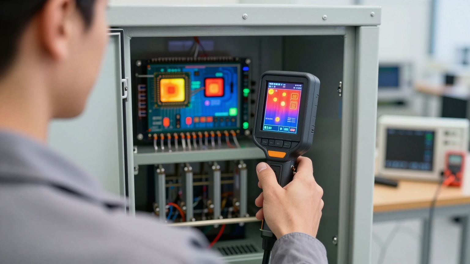
- Sensor Placement: For initial validation, place multiple thermocouples inside the cabinet: one near the cooling unit’s air outlet, one near the air inlet at the top, and several near the most critical heat-generating components (CPUs, VFDs, power supplies).
- Acceptance Test: Power on the system under a realistic or maximum heat load. Log the temperatures for several hours to confirm that all points remain within their safe operating limits and that the temperature gradient across the cabinet is minimal.
- Condensate Management: Ensure any condensate drain lines are properly routed and are not kinked or blocked.
-
Maintenance Planning
- External Coil Inspection: Schedule periodic inspections of the external (condenser) coil. In dusty or dirty environments, it must be cleaned to maintain heat transfer efficiency.
- Fan and Gasket Check: During inspection, verify that all fans are operational and that the mounting gasket remains pliable and free of cracks.
Frequently Asked Questions (FAQ)
1. Can’t I just use a larger heat sink or a heat exchanger?
A heat sink or heat exchanger can only cool the interior to a temperature *above* the outside ambient air. If your components must be kept at or below ambient, or if solar loading significantly heats the cabinet’s exterior, these passive methods will fail. They are only suitable for low power densities in moderate climates.
2. How do you prevent condensation inside a sealed cabinet?
Active air conditioners naturally dehumidify the air as it passes over the cold evaporator coil. This moisture is then collected and drained outside the cabinet. By keeping the internal air dry, the dew point is lowered, preventing condensation from forming on components, even when they are cooled significantly.
3. What if my cabinet is exposed to direct sun, dust, or salt spray?
This is precisely where a sealed, closed-loop system is required. The sealed design prevents dust, salt, and moisture from entering. For solar load, the cooling capacity must be calculated to include both the internal electronic heat load and the external heat gain from solar radiation. A properly sized Micro DC Aircon can handle these combined loads.
4. What is the most important measurement I need to take before selecting a cooler?
You need two key numbers: the total internal heat load (in watts) generated by all components, and the maximum expected ambient temperature combined with any solar/radiant heat gain. These two factors determine the required cooling capacity and prove whether an active solution is necessary.
5. How do I validate that I’ve achieved good temperature uniformity after installation?
The best method is a multi-point temperature study. Use data-logging thermocouples placed at various locations and heights within the cabinet. Run the system under full load on a hot day and analyze the data to ensure no single point exceeds the components’ maximum temperature rating and the overall temperature delta between the hottest and coldest spots is minimal.
6. Is a thermoelectric cooler a better choice than a DC air conditioner?
Thermoelectric (Peltier) coolers are solid-state and simple, but they are inefficient, especially with high heat loads or large temperature differences. A vapor-compression DC air conditioner is a much more efficient and powerful solution for demanding applications, providing more cooling per watt of power consumed.
Conclusion: The Right Fit for Mission-Critical Systems
For low-power electronics in temperate climates with no sealing requirements, simple fans and vents can suffice. For sealed cabinets with moderate heat loads and small temperature differentials, a thermoelectric cooler may be a viable option. However, when reliability is paramount and the operating environment is challenging, ensuring temperature uniformity in a sealed cabinet requires a more robust solution.
An active, vapor-compression system like a Micro DC Aircon is the best-fit technology when you face high internal heat loads, high ambient temperatures, significant solar gain, or a strict requirement to seal the enclosure against environmental contaminants. By creating a closed-loop, forced-convection air path, it actively eliminates hot spots, prevents uneven component aging, and provides a stable, predictable operating environment for your mission-critical electronics.
If you are designing a system with complex thermal challenges, our engineering team can assist with calculating heat loads and selecting the appropriate cooling solution tailored to your power constraints, enclosure geometry, and environmental conditions. Contact us to discuss your specific application.
0 条评论