Angle Lock: The decision is what to measure before sizing a sealed enclosure cooling system. Common failure modes are chronic overheating from undersized units and condensation from oversized, short-cycling units. The dominant constraint is maintaining the enclosure’s seal integrity against environmental hazards like dust and moisture.
A Practical Guide to Enclosure Heat Load Inputs
A critical control cabinet shutting down on a factory floor is more than an inconvenience; it’s a cascade of lost production, missed deadlines, and potential equipment damage. The root cause is often not the sophisticated electronics inside, but a failure to manage their environment. When an enclosure is sealed to protect against dust, moisture, or corrosive agents, heat becomes trapped. The decision of how to remove that heat is one of the most critical design choices an engineer makes. Get it wrong, and you face derating, premature component failure, and costly downtime. This article provides a systematic, data-driven framework for identifying the essential enclosure heat load inputs. By the end, you will be able to confidently gather the necessary data to perform accurate sealed enclosure cooling sizing, ensuring system reliability. In this guide, we prioritize a complete thermal picture over simplified calculations, because unaccounted-for heat sources are the primary cause of field failures.
Deployment Context: Where Thermal Management Fails
The need for precise thermal management appears in countless industrial settings. Consider two common scenarios where overlooking key heat load inputs leads to failure.
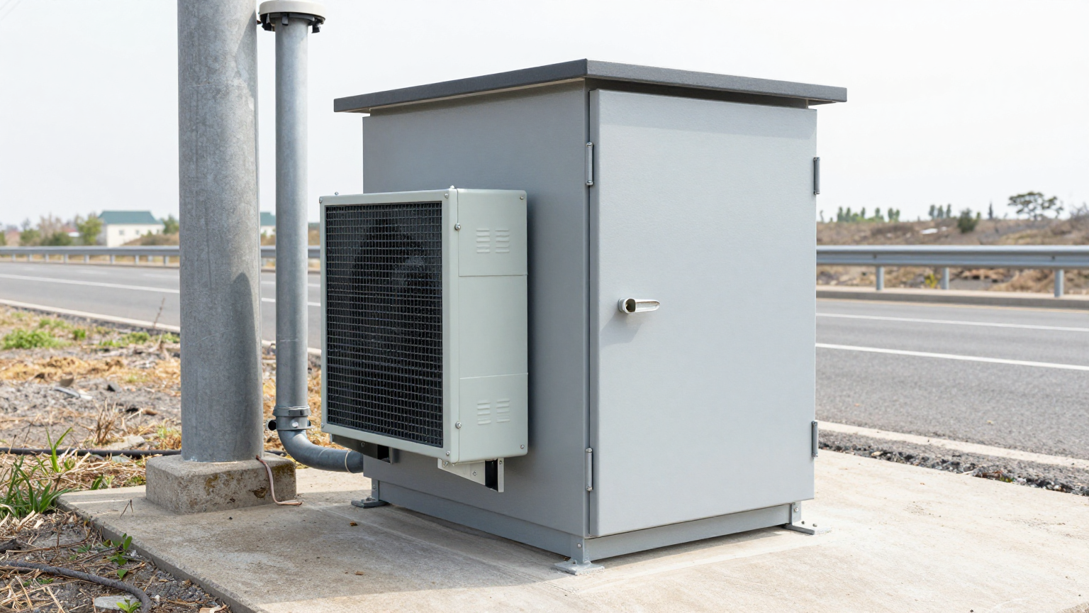
Scenario A: Roadside Telecom Cabinet
A sealed NEMA 4 cabinet houses networking switches and power supplies alongside a major highway. The initial thermal calculation only accounted for the heat generated by the electronics. However, the cabinet is south-facing with no shade. On a hot summer day, the intense solar radiation adds a massive, uncalculated thermal load. The internal temperature soars past the 60°C operating limit of the switches, causing intermittent network dropouts during peak sun hours. The constraint here was the unaccounted-for solar load, which overwhelmed the undersized cooling system.
Scenario B: Food Processing Plant Control Panel
A stainless steel control panel for a bottling line is located in a hot, high-humidity area that requires frequent washdowns. To meet IP66 standards, the enclosure is completely sealed. The designers correctly calculated the heat from the VFDs and PLCs. What they missed was the convective heat gain from the ambient environment; the room temperature near the ceiling where the panel was mounted often reached 45°C. The chosen heat exchanger, designed to keep the internal temperature only slightly above ambient, was useless. The internal components quickly overheated, tripping safety circuits and halting the line. The critical failure was misunderstanding the ambient temperature delta and the limitations of passive cooling.
Common Failure Modes & Constraints
Before sizing any cooling solution, it’s crucial to understand the symptoms and causes of thermal failure. These are the most common issues we see in the field, ranked by impact:
- Chronic Overheating → Underestimated Internal Load → Gradual degradation and premature failure of sensitive electronics like VFDs and power supplies.
- Intermittent Shutdowns → Unaccounted Solar Load → System works in the morning but fails in the afternoon sun, making the issue difficult to diagnose.
- Condensation & Corrosion → Oversized Cooler & Short Cycling → An oversized unit cools too quickly and shuts off, causing humidity to condense on components, leading to short circuits.
- Loss of Seal Integrity → Improper Gasketing/Mounting → Dust and moisture enter the cabinet, defeating the purpose of a sealed enclosure and fouling the cooling unit’s coils.
- Cooling Unit Overload → Blocked Air Filters/Coils → Lack of maintenance in dusty environments reduces cooling efficiency until the system can no longer keep up with the load.
- Power Supply Faults → High Inrush Current → The cooling unit’s startup current overloads the DC power bus, causing wider system instability.
- Reduced Performance → High Ambient Temperatures → The cooling unit itself derates in extreme heat, delivering less cooling capacity when it’s needed most.
- Nuisance Tripping → Incorrect Sensor Placement → The thermal sensor is placed in a cool spot, allowing other areas of the cabinet to overheat without detection.
Engineering Fundamentals: The Path of Heat
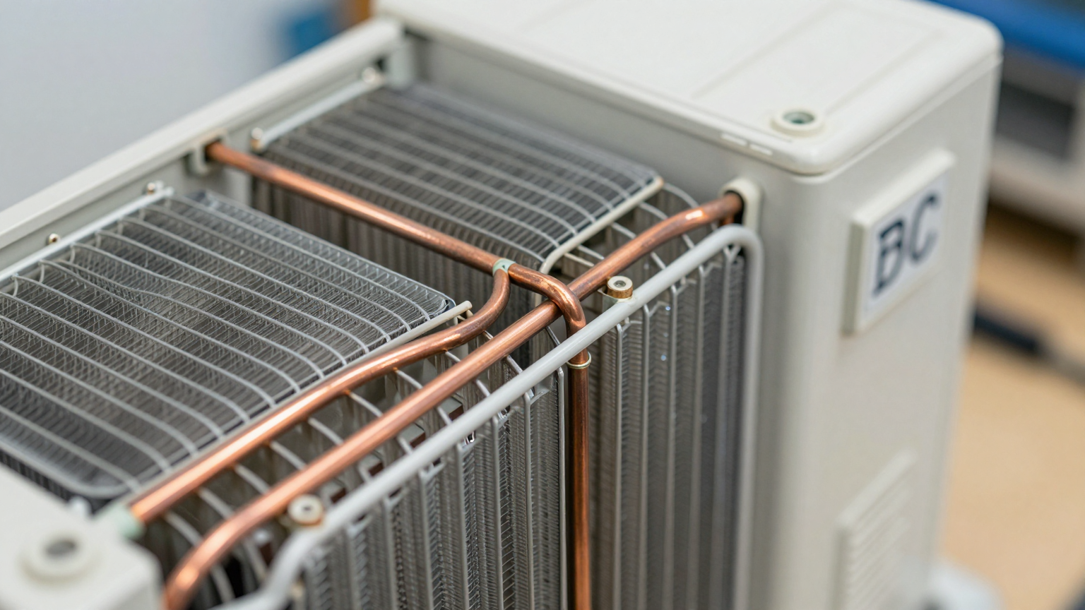
Effective sealed enclosure cooling is about creating a predictable path for heat to exit the system while preventing outside contaminants from entering. This is achieved with a closed-loop cooling design. The internal air is circulated within the enclosure, passed over a cold heat exchanger (the evaporator coil of an air conditioner), and then redistributed over the heat-generating components. The cooling unit absorbs this heat and rejects it into the ambient environment outside the enclosure.
This closed-loop approach is fundamental to maintaining a NEMA or IP rating. Cutting a hole for a simple fan and filter compromises the seal, allowing dust, humidity, and corrosive gases to enter freely. An active, closed-loop system like a Micro DC Aircon maintains the integrity of the seal by creating two separate air paths: one for the cool, clean internal air and another for the ambient air used to carry heat away from the condenser.
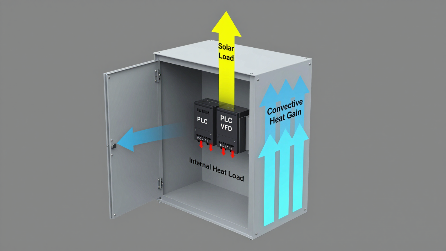
A common misconception is that if the internal heat load is, for example, 300 watts, a 300-watt cooler is sufficient. This is incorrect. This calculation ignores all other enclosure heat load inputs. Heat will always try to enter the enclosure from a warmer ambient environment (convection), and direct sunlight can add hundreds of watts of thermal energy (radiation). A proper sizing calculation must sum all internal and external heat gains to determine the total load the cooling unit must overcome.
Key Specifications for Sizing
Before selecting a cooling series, you must have your requirements clearly defined. For compact, sealed enclosures powered by a DC bus, you will need to confirm which specifications are non-negotiable. The table below shows typical parameters for a vapor-compression series like the Micro DC Aircon. Use it as a guide to frame your own project’s go/no-go criteria.
| Specification | Typical Range / Options | Why It’s a Go/No-Go Gate |
|---|---|---|
| Input Voltage | 12V / 24V / 48V DC | Must match the available DC power bus in the enclosure. Mismatched voltage is a non-starter. |
| Nominal Cooling Capacity | 100W – 900W | Must exceed the total calculated heat load (internal + external) with a safety margin of 15-20%. |
| Refrigerant Type | R134a / R290 / R1234yf | Driven by regional regulations and environmental policies. R134a is common, while others offer lower GWP. |
| Control System | Integrated PCB with variable-speed control | Variable-speed compressors and blowers are critical for efficiency and preventing short-cycling. |
| Physical Footprint | Varies by model | The unit must physically fit on or within the enclosure without obstructing access or critical components. |
| Operating Temperature | Depends on configuration | The unit must be rated to operate reliably at the maximum expected ambient temperature. |
Reading these specs is about matching constraints. First, lock in your voltage. Second, ensure the cooling capacity range covers your calculated total heat load. Finally, confirm that the physical dimensions and operating temperature range are compatible with your deployment environment.
Engineering Selection Matrix: Logic Gates for Sizing
An engineer’s selection process is a series of logic gates. Here’s how to navigate the primary decisions for sealed enclosure cooling.
Logic Gate 1: Passive vs. Active Cooling
- Constraint Gate: Maximum Allowable Internal Temperature vs. Maximum Ambient Temperature.
- Decision Trigger: If the maximum allowable internal temperature for your components is less than 10-15°C above the maximum possible ambient temperature, passive methods like fans or simple vents (for unsealed enclosures) will be insufficient.
- Engineering Resolution: The system requires a closed-loop cooling solution to maintain the temperature delta and the enclosure seal.
- Integration Trade-off: This moves the design from a simple, low-cost component (a fan) to a more complex subsystem with its own power and mounting requirements. However, it’s the only way to guarantee performance in a sealed system.
Logic Gate 2: Heat Exchanger vs. Active Air Conditioning
- Constraint Gate: Target Internal Temperature vs. Ambient Temperature.
- Decision Trigger: If the required internal enclosure temperature must be at or below the maximum external ambient temperature, a heat exchanger will not work. Heat exchangers can only keep the inside slightly warmer than the outside.
- Engineering Resolution: You must use an active, refrigerant-based system. A vapor-compression air conditioner is the only technology that can create an internal environment cooler than the ambient air. This is a critical step in the sealed enclosure cooling sizing process.
- Integration Trade-off: An active air conditioner consumes more power than a heat exchanger and introduces condensation management. However, it provides deterministic cooling performance regardless of ambient temperature fluctuations (within its operating range).
Logic Gate 3: Calculating Total Heat Load
- Constraint Gate: Total Heat Load vs. Nominal Cooling Capacity.
- Decision Trigger: The total heat load is the sum of three distinct inputs: 1) Internal Heat Load (from all electronics), 2) Convective Heat Gain (heat transfer through enclosure walls from hot ambient air), and 3) Solar Heat Gain (radiant energy from direct sunlight).
- Engineering Resolution: You must identify and quantify all three enclosure heat load inputs. Sum them to find the total watts of heat to be removed. Select a cooling unit with a nominal capacity that exceeds this total by at least 15-20% to account for minor inefficiencies and performance degradation over time.
- Integration Trade-off: Accurately measuring these inputs requires more upfront work than simply reading component datasheets. It may involve using thermal cameras or placing thermocouples at the deployment site. This initial investment prevents much costlier field failures and redesigns.
Implementation & Verification Checklist
Once you’ve selected a cooling unit, correct implementation is paramount. Follow this checklist to ensure reliability.
-
Mechanical Installation
- Mounting: Ensure the mounting surface is flat and rigid. Use all specified mounting points to prevent vibration.
- Sealing: Verify the gasket provides complete, uniform compression. A torque wrench is recommended for securing fasteners to the manufacturer’s specification. Perform a smoke test or light test to check for any gaps in the seal.
- Airflow Integrity: Confirm that the internal and external airflows are not obstructed. There should be several inches of clearance around both the intake and exhaust vents.
-
Electrical Connection
- Power Budget: Use dedicated wiring of the appropriate gauge for the cooler’s maximum current draw. Do not tap power from sensitive PLC or sensor lines.
- Circuit Protection: Install the recommended fuse or circuit breaker to protect both the cooling unit and the main power system.
- Wiring: Ensure all connections are secure and routed away from sharp edges or high-heat components.
-
Thermal Verification
- Sensor Placement: Place the primary control thermostat sensor near the top of the enclosure, in the return air path to the cooler, to get an accurate reading of the hottest air.
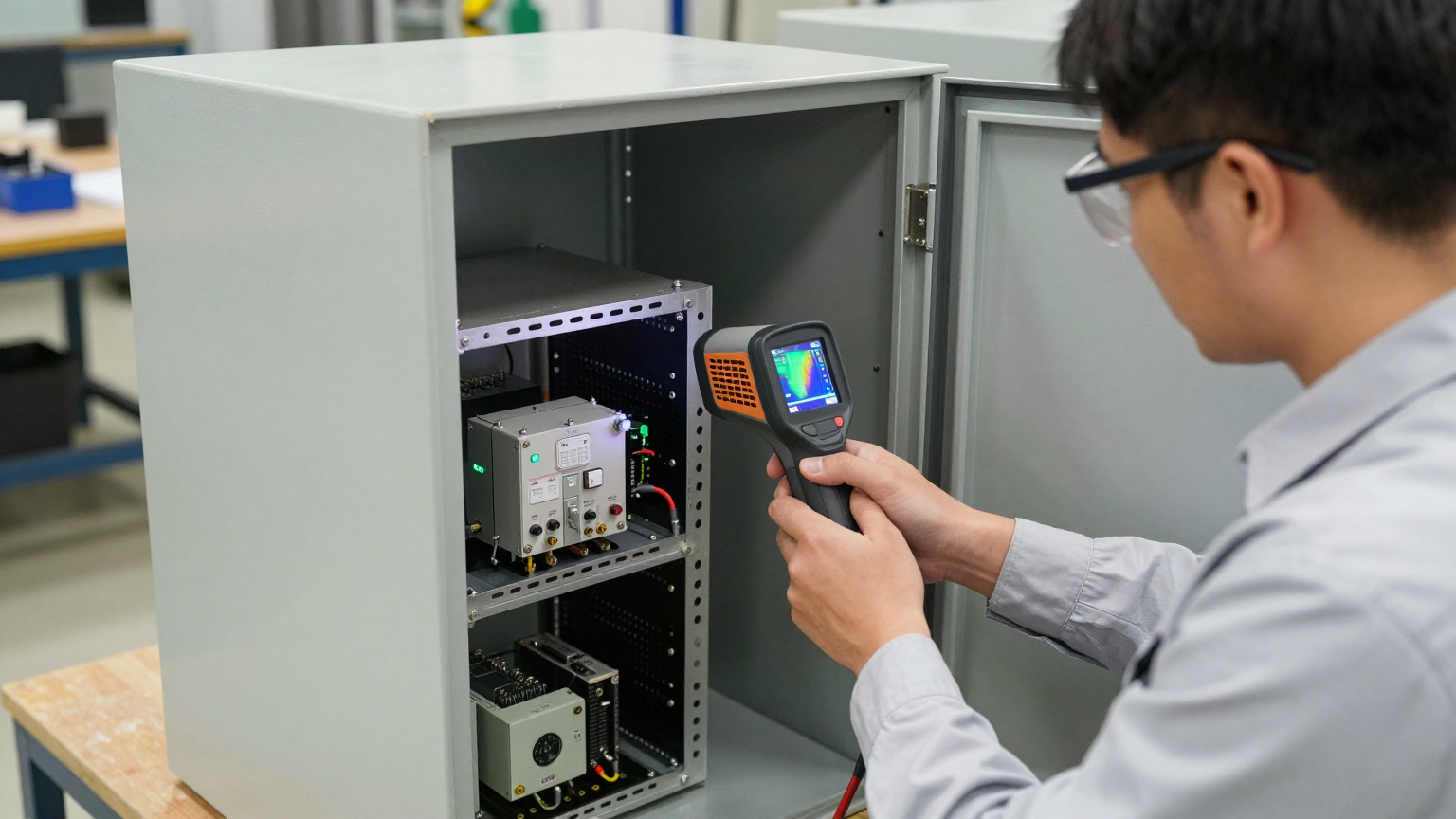
- Acceptance Test: After installation, run the system under full load. Use a thermal camera or multiple thermocouples to verify that temperatures are stable and within spec across all critical components, eliminating hot spots.
-
Maintenance Planning
- Access: Ensure the enclosure’s final placement allows for access to the cooling unit’s external coils for cleaning.
- Inspection Triggers: Set a periodic maintenance schedule (e.g., quarterly) to inspect and clean the condenser coils, especially in dusty or oily environments.
Frequently Asked Questions (FAQ)
1. What is the first thing I must measure before considering any cooling hardware?
Measure the worst-case ambient temperature at the exact location where the enclosure will be installed. Don’t use the weather report; use a thermometer next to the machine or on the pole in the sun. This is the single most important data point.
2. How do I estimate the solar load if I don’t have complex software?
As a conservative rule of thumb for a standalone cabinet in direct sun, you can add a significant heat load, often several hundred watts, depending on the enclosure’s surface area, color, and location. Darker, larger enclosures absorb more heat. This is a critical part of identifying enclosure heat load inputs.
3. Should I choose a heat exchanger or an air conditioner for my sealed enclosure?
If you need the internal temperature to be below the outside ambient temperature, you must use an air conditioner. A heat exchanger can only keep the inside slightly hotter than the outside.
4. How do I manage condensation with an active air conditioner?
Properly sized, variable-speed air conditioners minimize condensation by avoiding drastic temperature swings and short-cycling. Most industrial units also have integrated condensate management systems to evaporate and remove any moisture that does form.
5. My enclosure has to be IP66 rated. How does a cooling unit affect that?
A properly installed closed-loop air conditioner is designed to maintain the enclosure’s rating. It requires a cutout, but the unit’s integrated gasket and mounting system are engineered to create a watertight and dust-tight seal against the enclosure wall.
6. What’s more important: total cooling capacity (Watts) or airflow (CFM)?
Both are important, but you size the system based on cooling capacity (Watts) first. The capacity must be sufficient to remove the total heat load. The airflow (CFM) then determines how effectively that cooling is distributed throughout the enclosure to eliminate hot spots.
7. How do I validate that the cooling solution is working correctly after installation?
The best method is to use a thermal imaging camera under full operational load on a hot day. This will visually confirm that the temperature is uniform and that there are no hot spots on critical components. Data logging with multiple thermocouples is also an excellent validation method.
Conclusion: From Measurement to Reliability
A reliable sealed enclosure cooling system is not the result of a simple catalog selection. It’s the outcome of a methodical engineering process that begins with a thorough and honest assessment of all thermal inputs. By moving beyond just the internal component heat and rigorously accounting for convective and solar loads, you shift from reactive problem-solving to proactive design. This approach is the best fit for critical applications where downtime is not an option and equipment longevity is paramount. It may not be the right path for non-critical systems in climate-controlled rooms, where simpler solutions may suffice.
Understanding your enclosure heat load inputs is the foundation of effective thermal management. If you are designing a system with challenging power constraints, a compact footprint, or deployment in a harsh environment, our engineering team can help you navigate the sizing and selection process. Contact us to discuss your specific project requirements.


0 条评论