Field Snapshot: Sizing a Controlled Cooling Therapy Device
We were on-site with an OEM developing a new portable medical device. For their temporary therapeutic interventions, the goal was controlled, stable cooling—not aggressive overcooling. The engineering team was struggling to move past the prototype stage because their existing thermal solution, a thermoelectric cooler, was generating excessive waste heat and couldn’t maintain temperature stability once the ambient environment warmed up. They needed a compact, efficient, and precise cooling subsystem. This field note outlines the decision-making process for integrating a micro-compressor-based chiller, focusing on the critical gates that determine if this technology is the right fit for a controlled cooling therapy device.
First Checks: Scoping the Thermal Loop
Before evaluating specific hardware, we always start with the foundational constraints of the thermal system. Getting these wrong is the most common reason for project delays.
- Check: Total Thermal Load. Why: This is the total heat energy the system must remove. It includes heat from the patient contact point, electronics, and any parasitic heat gain from the environment. What it suggests: If your continuous thermal load exceeds the cooler’s capacity, you will never reach or maintain your target temperature. For this class of device, we were targeting a load at or below 450W.
- Check: Power Budget & Stability. Why: Miniature compressors have a significant peak current draw during startup. What it suggests: The power supply unit (PSU) must be rated for the peak load, not just the steady-state draw. The 24VDC supply needed to handle peaks up to 15A without voltage sag, which could otherwise cause the compressor to fault or fail.
- Check: Ambient Operating Environment. Why: A direct expansion (DX) cooler doesn’t make heat disappear; it moves it to a condenser, which then dissipates it into the surrounding air. What it suggests: A high ambient air temperature reduces the temperature differential, lowering the net cooling capacity. The system’s performance must be evaluated based on its worst-case operating environment, not just a lab bench.
- Check: Required Temperature Stability. Why: The therapeutic application dictates the required precision. What it suggests: If the application requires tight control, such as +/- 0.5°C, the entire thermal loop—including the pump, tubing, and heat exchanger—must be designed to support that stability. The chiller itself is only one part of the equation.
Common Failure Modes and Constraints
In the field, we see recurring issues when integrating active cooling. Here are the most common symptoms and their underlying causes.
- Symptom: Fails to reach temperature setpoint. Likely cause: The actual thermal load is higher than the specified 450W capacity, or the ambient temperature is too high, reducing the system’s effectiveness. Why it matters: An inability to reach the therapeutic temperature renders the device ineffective.
- Symptom: Intermittent system shutdowns. Likely cause: The 24VDC power supply cannot handle the 15A peak current during compressor startup, leading to a temporary voltage drop that triggers a fault in the controller. Why it matters: This creates an unreliable device, which is unacceptable for medical applications.
- Symptom: Temperature overshoots or oscillates. Likely cause: An improperly tuned control loop (via PWM/Serial) or an external circulation pump that is either oversized or undersized for the thermal loop. Why it matters: Lack of stability can compromise the therapeutic protocol, which often depends on maintaining a precise temperature.
- Symptom: Excessive condensation on coolant lines. Likely cause: Uninsulated tubing carrying cold fluid through a warmer, more humid section of the device. Why it matters: Condensation introduces a risk of moisture damage to sensitive electronics within the enclosure.
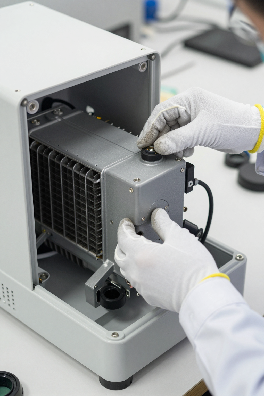
- Symptom: Noticeable vibration or humming. Likely cause: The micro-compressor’s vibrations are being directly transferred to the device chassis instead of being absorbed by isolation grommets. Why it matters: In a patient-facing device, unexpected noise and vibration can cause discomfort and a perception of poor quality.
- Symptom: Gradual decline in cooling performance over time. Likely cause: Dust and debris accumulating on the condenser fins, obstructing airflow. A secondary cause could be slow coolant loss from improperly seated quick-disconnect fittings. Why it matters: This points to a maintenance issue that can lead to premature field failures if not addressed.
Decision Gates for Active Cooling Integration
When does a micro-compressor system become the primary candidate? The decision typically hinges on three key gates.
Gate 1: Is Active, Dynamic Cooling Required?
- Constraint: The thermal load is not constant, or the device must operate continuously for extended periods.
- Decision Trigger: This requirement often rules out passive solutions like phase-change materials, which have a finite cooling capacity and cannot be actively controlled.
- Engineering Resolution: Adopt an active cooling system built around a variable-speed micro-compressor. This allows the cooling power to be modulated to precisely match the thermal load in real time.
- Integration Trade-off: The system will now require a dedicated power source, produce some operational noise (typically < 45 dBA), and require management of its exhaust heat.
Gate 2: Is High Precision a Non-Negotiable Requirement?
- Constraint: The therapeutic protocol demands temperature stability of +/- 0.5°C or better.
- Decision Trigger: Many simpler cooling technologies, like Peltier (thermoelectric) coolers, struggle to maintain this level of precision under varying loads and ambient conditions. They also tend to have a lower Coefficient of Performance (COP), meaning they generate more waste heat for a given amount of cooling.
- Engineering Resolution: A DX micro-chiller with a sophisticated control interface (PWM/Serial) provides the ability to make fine adjustments to the compressor speed, enabling tight temperature regulation.
- Integration Trade-off: Achieving this stability requires the OEM’s control system to be properly integrated and tuned. The overall system performance is dependent on the entire thermal loop, not just the chiller module.
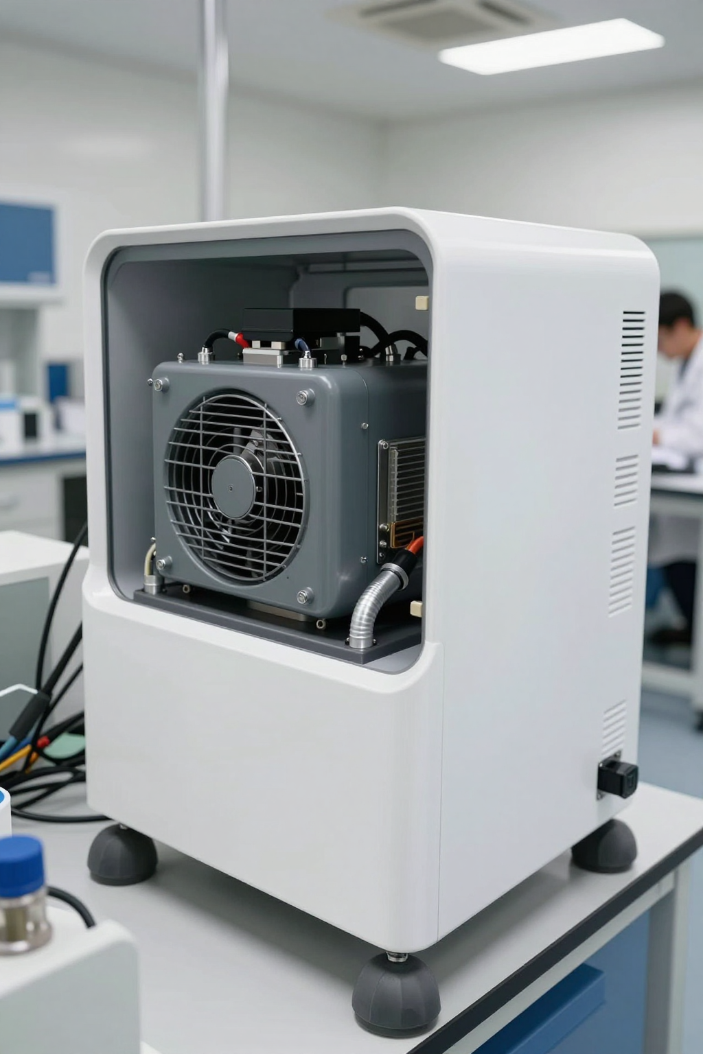
Gate 3: Are Size and Portability Critical Design Factors?
- Constraint: The final device must be portable or fit within a tightly constrained enclosure.
- Decision Trigger: Traditional refrigeration systems are too large and heavy. Passive systems can be bulky for a given thermal capacity.
- Engineering Resolution: A highly compact chiller module, with dimensions around 150 x 120 x 100 mm and a weight of approximately 2.5 kg, becomes a viable path forward.
- Integration Trade-off: The small form factor requires disciplined thermal design. Airflow over the condenser is critical, and obstructing it can quickly degrade performance. Careful component placement is essential.

Integration Notes: Field Observations
These are not installation steps but rather hard-won lessons from integrating these systems in the field.
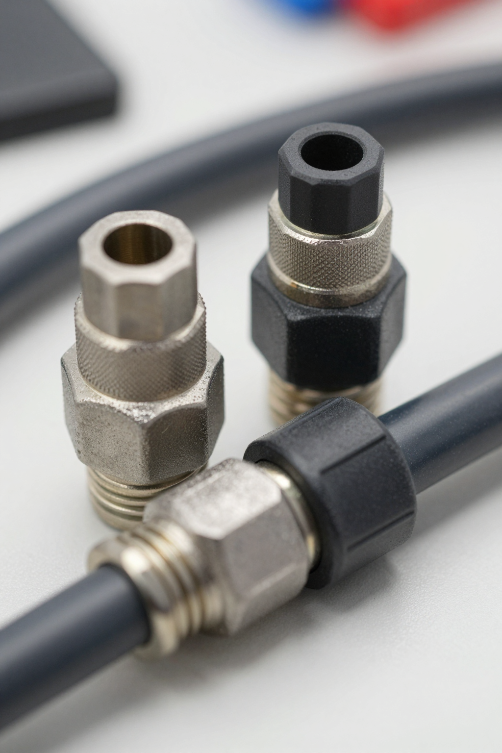
- Mechanical: The compressor generates small vibrations. Always use the supplied isolation grommets to mount the unit. Do not bolt it directly to the main chassis. Ensure you leave adequate clearance around the condenser for unobstructed airflow—recycling hot exhaust air is a common cause of performance issues. The non-drip, quick-disconnect fittings are robust but must be fully seated to prevent slow leaks.
- Electrical: Use a dedicated, low-noise PSU. Sharing power rails with sensitive measurement electronics can introduce electrical noise. The power connector should be a locking type to prevent accidental disconnection due to vibration. Plan for the 15A startup current; a soft-start feature in the control logic can be beneficial.
- Thermal: The number one thermal rule is to never allow condenser exhaust air to be drawn back into the condenser intake. This creates a feedback loop that rapidly diminishes cooling capacity. All coolant tubing running from the chiller to the application point should be insulated, especially in humid environments, to prevent thermal losses and condensation.
- Maintenance: Design for access. An engineer should be able to inspect the condenser fins for dust buildup and check the coolant reservoir without a complete teardown. Using distilled water or the approved coolant is critical; other fluids can cause buildup or corrosion inside the heat exchanger.
Frequently Asked Questions
Here are some common questions we encounter during the design phase for a controlled cooling therapy device.
- Our power source is a 24V battery pack. Is that a problem?
Not necessarily, but the battery management system (BMS) must be able to safely deliver the peak startup current without a significant voltage drop. An undervoltage condition can damage the compressor driver or cause unexpected shutdowns. - The spec sheet says +/- 0.5°C stability. Is that guaranteed at the patient contact point?
That stability is for the chiller unit itself. The final stability at the point of application depends on the entire thermal loop you design: the efficiency of your heat exchanger, the flow rate of your pump, and how well the tubing is insulated. - What happens if our peak load occasionally spikes above 450W?
The system will attempt to keep up, but the coolant temperature will likely rise above the setpoint during the spike. If the overload is sustained, the system will not be able to catch up, especially in warmer ambient conditions. It is not designed to be continuously overdriven. - We have a preferred coolant fluid for our other systems. Can we use it here?
It’s strongly advised to use only distilled water or fluids explicitly approved for the unit. Unapproved coolants can have different thermal properties, affecting performance, and may contain additives that cause corrosion or clog the micro-channels in the heat exchanger. - The device will be used in a quiet patient room. How loud is ‘under 45 dBA’ in practice?
It’s comparable to a quiet office environment or a modern refrigerator. It is not silent. The sound is primarily from the small condenser fan and the low hum of the micro-compressor. This is a significant improvement over larger systems but a key difference from truly silent passive solutions. - Does the unit include a circulation pump, or is that on our BOM?
This unit is a chiller core. A suitable external pump to circulate the coolant is a required component that you will need to specify and add to your bill of materials.
Conclusion: When a Micro-Chiller is the Right Fit
For a controlled cooling therapy device, the decision to use a micro-compressor chiller comes down to a clear set of needs. If your application requires dynamic heat removal up to 450W, demands precise temperature stability, and must fit within a compact, portable form factor, then this technology is often the most direct path to a reliable solution.
However, if your thermal load is very low, your stability requirements are loose, or absolute silence is a primary design constraint, then alternatives like thermoelectric or passive phase-change systems might be considered. For applications that fit the profile discussed here, the AlphaCooler series provides a robust foundation. You can find more detailed specifications on the AlphaCooler micro-chiller product page.


0 条评论