Field Snapshot: Diagnosing the Hidden Condensation Risk in Battery Pack Cooling
We were on-site reviewing a series of intermittent faults in a containerized battery energy storage system (BESS). The system performed reliably through the summer, but as the cooler, damp weather of autumn arrived, the battery management system (BMS) began logging sporadic communication errors and isolation warnings. The initial assumption was overheating, but the logs showed cell temperatures were well within nominal limits. The real issue was more subtle. The seasonal transition—cool nights followed by warmer, humid days—was creating a significant condensation risk in battery pack cooling. The existing air-to-air heat exchangers were dropping the internal component surfaces below the dew point, causing moisture to form on sensitive electronics. This field note walks through the diagnostic process and the decision gates that lead to specifying an active, variable-speed DC cooling solution. By the end, you’ll have a clearer framework for when passive or simple on/off cooling is insufficient for protecting sensitive battery systems.
First On-Site Checks
When facing intermittent environmental faults, our first step is to establish a baseline by correlating system behavior with external conditions. Before modifying the hardware, we focus on data.
- Check: Correlate BMS fault logs with historical weather data, specifically ambient temperature and relative humidity.
- Why: We are looking for patterns that link system errors to specific environmental conditions, such as a sharp temperature drop overnight or a rapid increase in morning humidity.
- What it suggests: If faults cluster during periods of high humidity and moderate temperatures, it points away from simple overheating and toward a dew point problem.
- Check: Inspect the enclosure’s seals, cable glands, and any ventilation ports for signs of water ingress.
- Why: It’s critical to differentiate between moisture from an external leak and moisture forming internally. A physical inspection rules out the simplest explanation first.
- What it suggests: Clean, intact seals with moisture present on internal components (like busbars or PCB conformal coatings) strongly indicate condensation is the source.
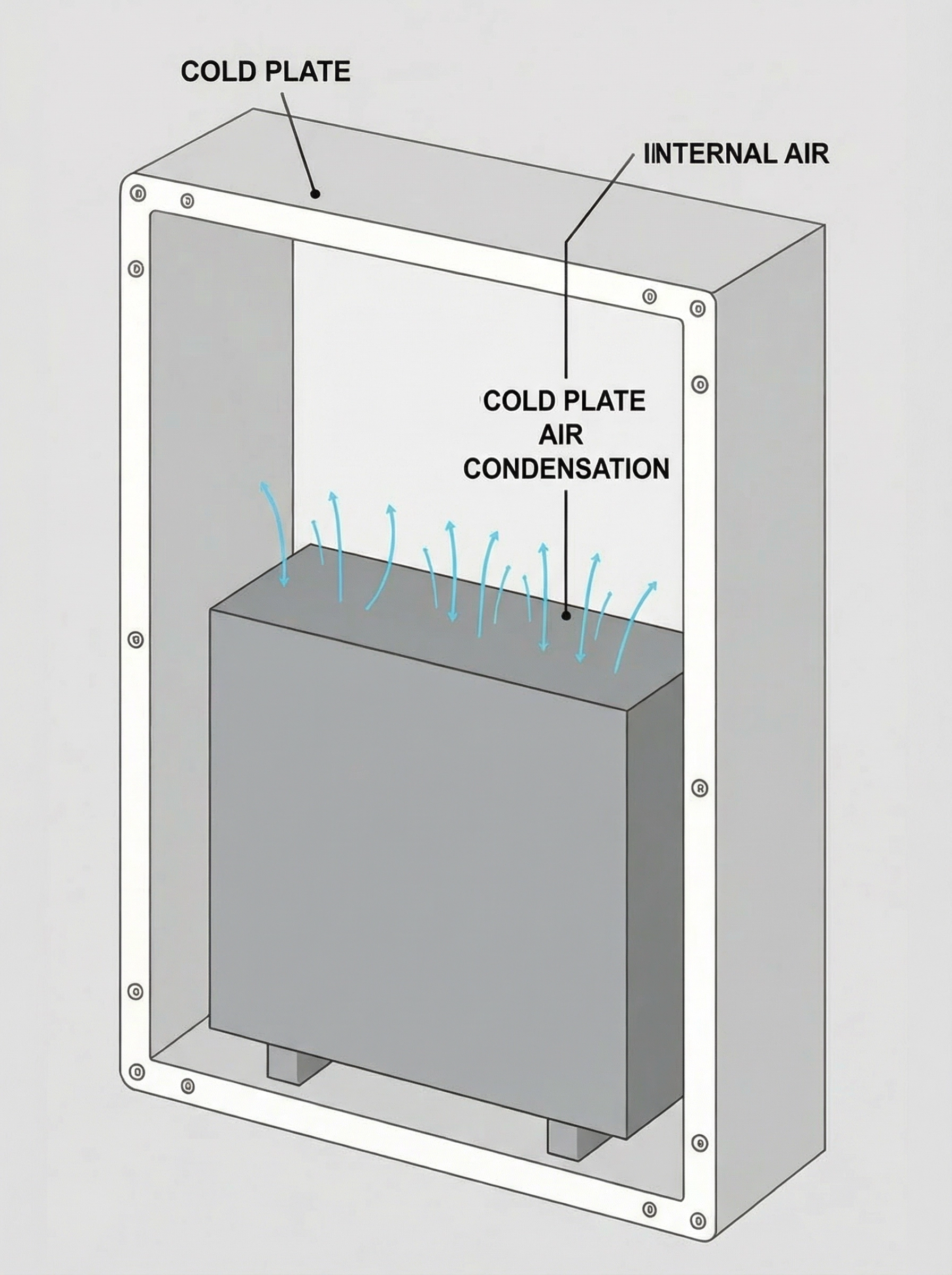
- Check: Deploy temporary sensors to log the surface temperature of the cold plate or heat sink alongside internal enclosure humidity.
- Why: The core of condensation is a surface temperature falling below the air’s dew point. We need to measure this directly, as air temperature alone is not enough.
- What it suggests: If the cold plate surface is consistently several degrees colder than the internal air and faults occur when internal humidity is high, the cooling system itself is likely the cause of the condensation.
Failure Modes & System Constraints
Condensation-related failures are often misdiagnosed because they don’t present as a clear thermal runaway event. They are slow, subtle, and corrosive. Understanding these failure modes is key to justifying a more robust thermal management strategy.
- Symptom: Intermittent, non-repeatable communication faults from the BMS.
- Likely Cause: Moisture forming on connector pins or exposed traces, creating temporary, low-impedance paths that disrupt sensitive data lines.
- Why it matters: Unreliable communication can lead to the BMS unnecessarily taking a battery string offline, reducing system availability and performance.
- Symptom: Accelerated corrosion on busbars, terminals, or enclosure hardware.
- Likely Cause: Condensate acts as an electrolyte, enabling galvanic corrosion between dissimilar metals or creating high-resistance oxide layers.
- Why it matters: Increased resistance generates localized hot spots during high-current charge/discharge cycles, posing a safety risk and degrading battery life.
- Symptom: Nuisance trips from ground fault detection (GFD) systems.
- Likely Cause: Widespread condensation can create unintended electrical paths to the chassis, which GFD systems correctly identify as a fault.
- Why it matters: While the system is functioning as designed, the root cause is poor environmental control. Frequent shutdowns for a non-critical fault reduce the system’s economic viability.
- Symptom: Cooling system appears to work (fans run, heat is rejected), but moisture problems persist or worsen.
- Likely Cause: A simple, high-capacity cooling system can aggressively drive surface temperatures below the dew point, actively pulling moisture out of the air.
- Why it matters: This shows that just adding more cooling power can be counterproductive. The system requires intelligent control, not just brute force.
Decision Gates for Active Thermal Management
Moving from passive solutions or simple fans to an active refrigeration cycle seems like a major step. The decision is typically forced by a series of engineering constraints that cannot be met any other way. Here are the common gates we evaluate.
Gate 1: The Ambient Temperature Constraint
- Constraint: The system must maintain an internal battery temperature (e.g., 25°C) that is consistently at or below the peak daytime ambient temperature.
- Decision Trigger: When the ambient temperature (T_ambient) is higher than the required internal temperature (T_internal), no passive or fan-based system can work. Heat transfer requires a positive temperature differential.
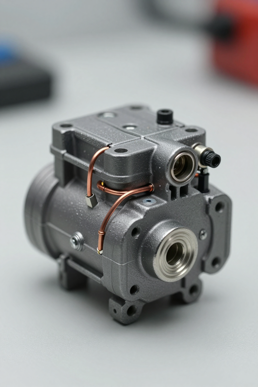
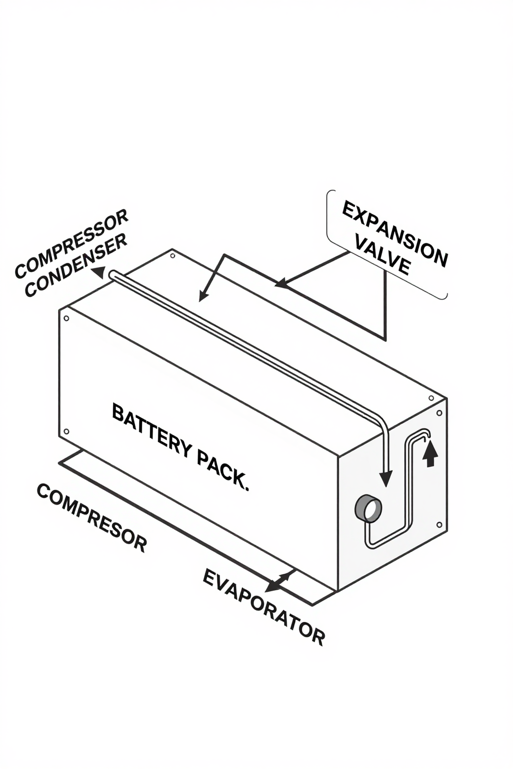
- Engineering Resolution: An active cooling system, such as one based on a miniature DC compressor, is required to create an artificial temperature gradient and move heat out of the enclosure against the natural flow.
- Integration Trade-off: This introduces power consumption, higher complexity, and the need for refrigerant management, but it’s often the only path to achieving the required performance.
Gate 2: The Peak Heat Load Constraint
- Constraint: The battery pack generates high, transient heat loads during rapid charging or discharging that must be removed quickly to prevent cell degradation.
- Decision Trigger: Passive systems with high thermal mass can absorb some peaks, but they recover slowly. Thermoelectric coolers (TECs) can respond quickly but often have a low Coefficient of Performance (COP), making them inefficient for removing high heat loads (typically over a few hundred watts).
- Engineering Resolution: A vapor-compression system with a capacity matched to the peak load, such as a 1200W miniature compressor, can provide the necessary cooling power with much greater efficiency than a TEC.
- Integration Trade-off: A compressor-based system has a higher initial component cost and a larger physical footprint than a TEC, but it significantly reduces the electrical power required for cooling, which can be a critical factor in the overall system energy budget.
Gate 3: The Dew Point Control Constraint
- Constraint: The system operates in an environment with variable humidity, and the internal component surfaces must be kept above the dew point at all times. This is the central challenge in managing the condensation risk in battery pack cooling.
- Decision Trigger: A simple on/off cooling system cannot modulate its intensity. When it runs, it may cool the evaporator to a fixed, low temperature that is frequently below the dew point.
- Engineering Resolution: A variable-speed DC compressor, controlled by a PWM or analog signal, allows for precise management of the evaporator temperature. The control logic can be programmed to target a surface temperature that is low enough to cool the batteries but high enough to stay safely above the calculated dew point.
- Integration Trade-off: This requires more sophisticated control logic and sensors (humidity, temperature) but directly solves the condensation problem, justifying the added complexity in high-reliability applications.
Integration Notes for Miniature DC Compressor Systems
Integrating a miniature vapor-compression cycle is not a simple drop-in replacement. It requires a system-level approach. These are not procedural steps but rather key considerations we’ve learned from field deployments.
Mechanical
- Vibration & Noise: While modern rotary compressors are relatively smooth, they still produce vibration. For sensitive electronics or applications with strict acoustic limits (systems rated around 58 dBA), proper vibration-damping mounts are essential.
- Weight & Layout: The compressor itself is compact, weighing around 2.2 kg, but the full system includes a condenser, evaporator, and tubing. The layout must ensure proper airflow over the heat exchangers and allow access for maintenance.
Electrical
- Power Stability: The system is designed for a nominal 48V DC supply. The controller can be sensitive to voltage instability. The power source must be robust enough to handle the maximum current draw of up to 15A, especially during startup, to avoid controller faults.
- Control Signal: The variable-speed capability is the key to managing condensation. Ensure the master system controller can provide a clean, stable PWM or analog signal to modulate the compressor speed accurately.
Thermal
- Heat Exchanger Sizing: The compressor’s cooling capacity is only realized if the condenser and evaporator are sized correctly. An undersized condenser, for example, will cause high head pressure and reduce both efficiency and reliability. This is a common point of failure in custom integrations.
- Refrigerant Management: The system uses R134a refrigerant. Proper charging is critical. Overcharging can lead to high pressures and liquid slugging on startup, which can damage the compressor. This is a significant condensation risk in battery pack cooling system integration that requires trained technicians.
Maintenance
- Leak Checks: While factory-sealed systems are reliable, field-integrated systems rely on fittings and brazed joints. These should be on a periodic inspection schedule to check for refrigerant leaks, which are the primary cause of performance degradation over time.
- Firmware: The compressor controller’s performance curves are optimized via its firmware. It’s good practice to check for updates, as these can improve efficiency, startup behavior, and fault detection.
Frequently Asked Questions (FAQ)
- How much power does a miniature compressor system consume?
- It’s variable. The power draw depends on the required cooling load. At full capacity, it can draw up to 15A at 48V, but the variable-speed control means it will only use the power needed to maintain the target temperature, making it more efficient than on/off systems during partial load conditions.
- Isn’t a compressor too noisy for our application?
- This depends on the noise budget. A typical unit runs at around 58 dBA. With proper mounting and acoustic insulation, this can be managed in many industrial applications, but it is not silent like a passive system.
- Why not just use a more powerful fan system?
- Fans are effective only when the ambient air is cooler than your target temperature. If you need to keep batteries at 25°C when it’s 35°C outside, no amount of airflow will achieve that. This is a fundamental limitation of convection-only cooling.
- How does this system perform in very cold weather?
- The operational range is typically from -20°C to 60°C. In cold environments, the challenge is often preventing liquid refrigerant from returning to the compressor on startup. Modern controllers have built-in logic to manage this, but it’s a key integration detail to review.
- What is the primary benefit over a thermoelectric (TEC) cooler?
- Coefficient of Performance (COP), or efficiency. For a given amount of heat removal, especially above a few hundred watts, a vapor-compression system uses significantly less electrical power than a TEC. This is critical in battery-powered applications where every watt matters.
- How do we control the cooling level to avoid condensation?
- Control is managed via an external signal (PWM or analog) to the compressor’s driver. By integrating humidity and temperature sensors, your master controller can implement a dew point avoidance algorithm, constantly adjusting compressor speed to keep surfaces cool but not condensing. This directly addresses the condensation risk in battery pack cooling.
Conclusion: Matching the Tool to the Environment
For battery systems deployed in stable, controlled environments, passive cooling or simple fan-based systems are often sufficient and reliable. However, for systems in the field, subject to dynamic thermal loads and wide swings in ambient temperature and humidity, a more intelligent approach is required. The decision to integrate an active, variable-speed cooling solution is driven by hard constraints: the need to cool below ambient, the demand for managing high peak loads efficiently, and the critical requirement to control surface temperatures to prevent condensation.
When these conditions are present, a miniature DC compressor-based system provides the necessary cooling power and, more importantly, the precise control needed to protect sensitive electronics from both heat and moisture. For engineers designing systems that face these challenges, exploring the capabilities of modern, compact cooling solutions is a logical next step. You can review the specifications for a system designed for these applications on our 48V miniature DC compressor product page.


0 条评论