Field Snapshot: When Forced Air Fails in Fast-Charging Battery Packs
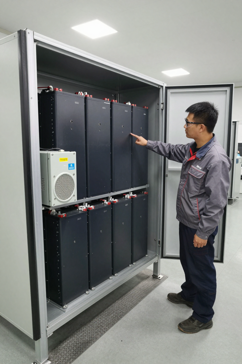
We were on-site with a client developing a compact, sealed energy storage system. The core of their design used several 48V battery modules, but they were hitting a wall during testing. During fast-charging cycles, the Battery Management System (BMS) would consistently trigger thermal protection and shut down the charge. The enclosure’s fans were running at full speed, but localized hot spots on a few cells were exceeding the safe operating threshold. Their constraints were tight: a sealed enclosure, no room for a larger air-cooled heat sink, and a need to maintain charge speed to meet product requirements. The core engineering challenge was clear: they needed a targeted, high-capacity cooling solution that could run efficiently on the existing 48V DC bus. This post outlines the decision-making process for integrating active cooling for 48V battery modules when conventional methods are no longer sufficient.
First Checks: Validating the Need for Active Cooling
Before replacing a cooling system, we establish a baseline. In situations like this, we start with a few key diagnostics to confirm that the problem isn’t a simple integration oversight. These checks help justify the move to a more robust thermal solution.
- Check: Airflow path analysis inside the enclosure. We use a thermal anemometer or even smoke pencils to visualize airflow from the existing fans. → Why: Obstructions or dead zones can starve specific modules of airflow, creating hot spots even when the fan’s CFM rating seems adequate. → What it suggests: If airflow is uniform but temperatures still climb, the issue isn’t distribution; it’s a lack of cooling capacity. The system has exceeded the thermal limits of forced air convection.
- Check: Thermal imaging under full load. We review thermal scans of the modules during the fast-charge cycle, specifically noting the temperature delta between the hottest cell and the average module temperature. → Why: This pinpoints whether the heat is uniform across the module or concentrated in a small area (high heat flux). → What it suggests: A high delta-T across a single module often means that general air cooling is inefficient. You end up over-cooling the entire enclosure just to manage one small, critical area. This points toward a direct-to-module cooling strategy.
- Check: BMS temperature logs versus ambient. We correlate the BMS temperature sensor data with the ambient temperature inside and outside the enclosure. → Why: This tells us how much work the current cooling system is doing. If the module temperature is rising even when the ambient air is relatively cool, it confirms the heat load is significant. → What it suggests: If the module temperature closely follows a rising ambient temperature, it indicates the system has no way to cool below ambient, a primary limitation of any fan-based system.
Common Failure Modes and System Constraints
When a battery’s thermal management system is undersized, it manifests in several ways that go beyond simple warning lights. These are common symptoms we see in the field that indicate a fundamental mismatch between the heat load and the cooling system.
- Symptom: Repeated, premature charge termination. → Likely Cause: The BMS is performing its safety function correctly, triggered by cells exceeding their maximum safe temperature. → Why it matters: This directly impacts the equipment’s availability and duty cycle, failing to meet operational requirements.
- Symptom: Fans operating at 100% duty cycle but module temperatures continue to rise. → Likely Cause: The total heat generated by the battery modules exceeds the heat dissipation capacity of the fan-and-heatsink system. The system has reached thermal saturation. → Why it matters: This is a clear sign that forced air is insufficient. No amount of additional airflow will solve the problem if the ambient air itself is too warm.
- Symptom: Noticeable performance differences between identical modules in the same array. → Likely Cause: Uneven cooling and persistent temperature gradients are causing some cells to age and degrade faster than others. → Why it matters: This reduces the effective service life of the entire battery pack, as the pack’s performance is limited by its weakest module.
- Symptom: System performance derates significantly in warmer operating environments. → Likely Cause: The cooling system is entirely dependent on a low ambient temperature to create a sufficient temperature differential for heat transfer. → Why it matters: The equipment is not environmentally resilient and cannot be deployed in a wide range of real-world conditions.
- Symptom: The enclosure’s internal ambient temperature is only a few degrees below the module’s trip temperature. → Likely Cause: The cooling system lacks the capacity to create a significant temperature difference (delta-T), leaving no thermal headroom for peak loads. → Why it matters: The system is running at the edge of its limits, making it vulnerable to any small increase in load or ambient temperature.
Decision Gates for Integrating a Vapor-Compression System
When the initial checks confirm that forced air is inadequate, the next step is to evaluate more advanced cooling technologies. This involves a series of decision gates that guide engineers toward the right solution based on hard constraints.
Gate 1: Target Temperature vs. Ambient Temperature
- Constraint: The battery module’s ideal operating temperature is close to, or even below, the maximum ambient operating temperature of the environment.
- Decision Trigger: When T_target ≤ T_ambient, all cooling technologies that rely on convection to ambient air (fans, heat sinks) are disqualified as primary solutions.
- Engineering Resolution: The system requires a refrigeration-based technology that can actively pump heat and create a temperature differential independent of the ambient air. This typically means a vapor-compression cycle or a thermoelectric (Peltier) cooler.
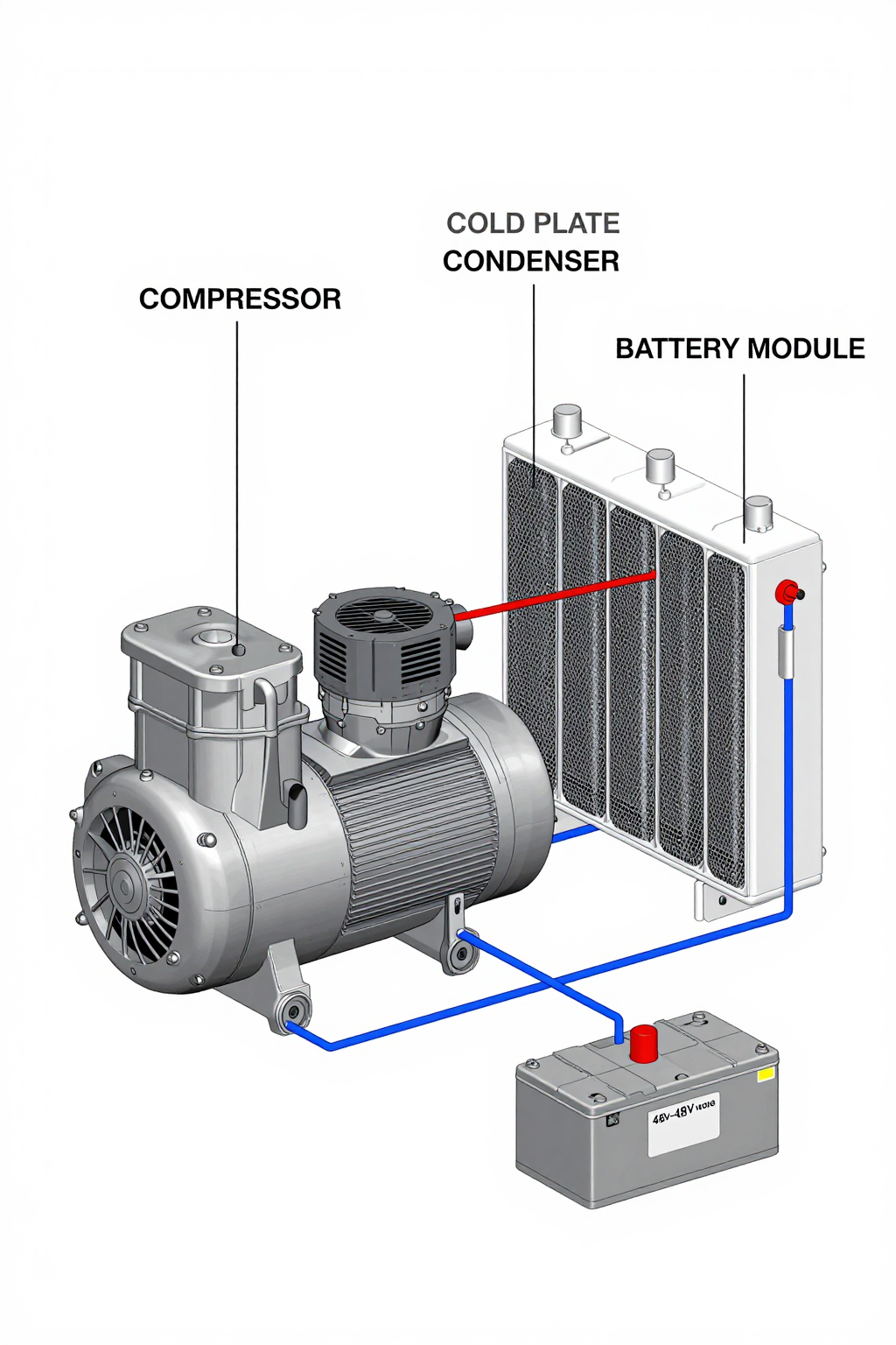
- Integration Trade-off: Moving to a refrigeration cycle introduces components like a compressor, condenser, and evaporator. While more complex than a fan, a miniature DC vapor-compression system offers a much higher cooling capacity for its size and power draw.
Gate 2: Heat Load Density and Location
- Constraint: The heat is not generated uniformly. Instead, intense hot spots appear on specific areas of the battery modules.
- Decision Trigger: Thermal imaging confirms a high heat flux in a concentrated area, while other parts of the system remain relatively cool.
- Engineering Resolution: Shift from cooling the entire enclosure’s air volume to a direct-contact cooling method. A liquid-cooled cold plate, attached directly to the module casing over the hot spot, is a common and effective solution. This cold plate becomes the evaporator in a vapor-compression loop.
- Integration Trade-off: Direct-to-module cooling is more mechanically involved, requiring tubing and a cold plate. However, it is vastly more efficient, as it removes heat at the source rather than trying to lower the temperature of the entire air mass within the enclosure. This often results in a lower net power draw for the thermal system.
Gate 3: Power Budget and Efficiency (COP)
- Constraint: The cooling system must run off the same 48V DC bus as the primary system, and the power budget is limited.
- Decision Trigger: The required cooling capacity (in watts) is high enough that a Peltier/TEC solution would be highly inefficient, drawing an excessive amount of current.
- Engineering Resolution: Compare the Coefficient of Performance (COP) of the available options. TECs are simple but their COP drops significantly as the heat load increases. A miniature DC compressor-based system maintains a much higher COP, delivering more cooling power for each watt of electrical input. For heat loads above 100W, the efficiency gains are substantial.
- Integration Trade-off: A miniature DC compressor has a higher upfront component cost than a TEC. However, its lower operating power consumption can be a critical advantage, preserving more of the power budget for the primary application and potentially allowing for a smaller, lighter power supply.
Integration Notes for Miniature DC Compressors
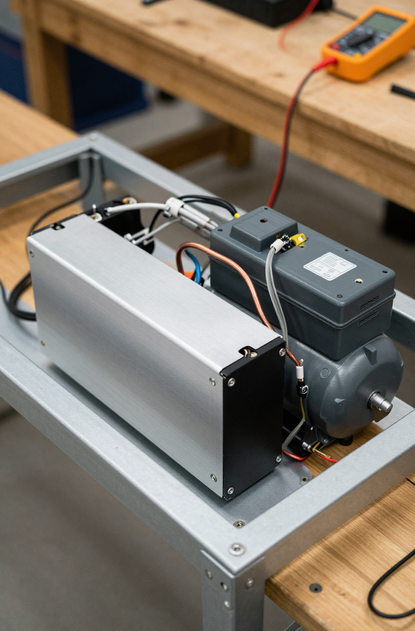
Integrating a vapor-compression system is not a drop-in replacement for a fan. It requires a system-level approach. These are some field notes from recent integrations.
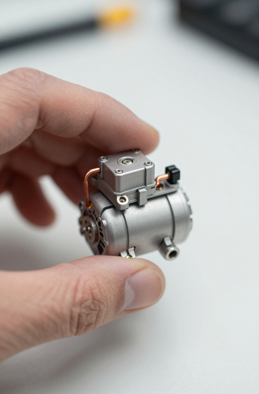
- Mechanical: The compressor itself is compact—small enough to fit in your palm—but it requires vibration-damping mounts to isolate it from the chassis. Refrigerant lines must be routed carefully to avoid sharp bends or kinks that could impede flow. The condenser, which dissipates the heat, needs access to an airflow path, often using a small, dedicated fan.
- Electrical: A key benefit is that these systems are designed to run directly from a 48V DC power source. The compressor’s variable-speed driver is typically controlled via a simple PWM signal or serial communication. This allows the BMS or a dedicated thermal controller to precisely match the cooling capacity to the real-time heat load, which is a major power-saving feature.
- Thermal: The evaporator is the “business end” of the system. This is almost always a custom-designed cold plate that provides a direct thermal path from the battery module casing to the refrigerant. Proper thermal interface material (TIM) between the cold plate and the module is critical for performance. The entire cold side, including the cold plate and refrigerant lines, should be insulated to prevent efficiency loss and manage condensation.
- Maintenance: Because the systems use a hermetically sealed, closed-loop refrigerant circuit, they are generally very low-maintenance, similar to a household refrigerator. The primary maintenance point is ensuring the condenser fins and fan remain clear of dust or debris that could reduce heat rejection performance.
Frequently Asked Questions (FAQ)
- Why can’t we just use more powerful fans?
Fans are effective only when the ambient air is cool enough to absorb the heat. If the ambient air is already warm, or if the heat is too concentrated (high heat density), even powerful fans cannot remove it fast enough. This is the primary reason to consider active cooling for 48V battery modules. - Is a Peltier (TEC) cooler a simpler alternative?
TECs are simpler mechanically, but they are often far less efficient (lower COP), especially for cooling loads over 100-150W. For a significant heat load from fast charging, a TEC would likely draw too much power from the 48V bus, making a miniature compressor a more energy-efficient choice. - How much cooling capacity is needed?
This is entirely dependent on the heat generated by your specific battery modules under worst-case (fast charge) conditions. The first step is to quantify that heat load in watts. Our miniature compressor systems can provide up to 450W of cooling, covering a wide range of applications. - Can this system integrate with our existing BMS?
Yes. The compressor’s driver accepts common control inputs like PWM or serial commands. A BMS that can output a control signal based on its temperature sensors can be used to regulate the compressor speed and manage the module temperature precisely. - What about condensation?
Any cooling system that can cool a surface below the dew point creates a risk of condensation. This is not unique to vapor compression. Proper system design, including insulating the cold plate and suction lines, is the standard engineering practice to manage this. - How compact is the compressor unit?
The compressor unit itself is small enough to be held in the palm of your hand. This compact form factor is what allows it to be integrated into tight spaces within or adjacent to existing battery enclosures where other cooling solutions might not fit.
Conclusion: The Right Tool for High-Density Heat Loads
Forced air cooling is reliable and cost-effective, but it has fundamental thermodynamic limits. When designs for 48V systems involve sealed enclosures, high-rate fast charging, and operation in varied ambient temperatures, those limits are often reached. The engineering decision to move to active cooling for 48V battery modules is triggered when you can no longer maintain the target temperature because of high heat density or high ambient temperatures.
A miniature DC vapor-compression system directly addresses these constraints. It is not a universal replacement for fans, but it is a targeted solution for applications where heat load and density have surpassed the capabilities of any other approach. By moving the heat with a refrigerant loop, it provides high-capacity, efficient, and controllable cooling that is independent of ambient conditions. If your battery module design is pushing the limits of passive cooling, exploring a compact vapor-compression solution may be the next logical step. For detailed specifications on a system designed for these applications, see our 48V Miniature DC Compressor.


0 条评论