Field Snapshot: How to Prevent Condensation in IVD Cooling Systems
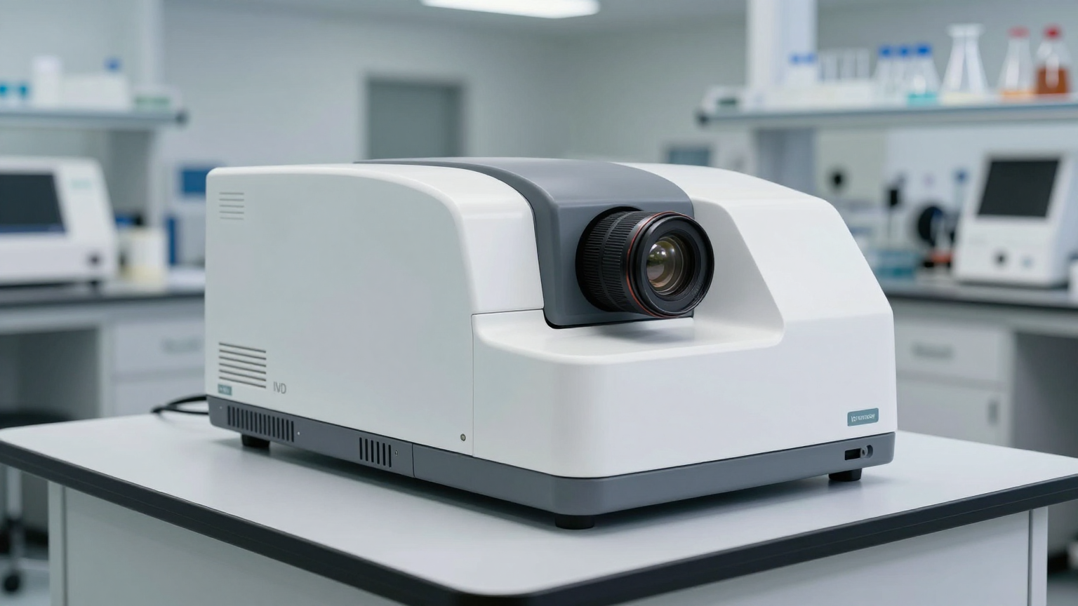
We were recently consulted on an integration project for an in-vitro diagnostic (IVD) analyzer where the engineering team had hit a frustrating roadblock. The sample chamber’s temperature control was performing perfectly, holding a stable setpoint. However, untreated ambient humidity and minor imperfections in the enclosure’s insulation were creating a persistent condensation risk on sensitive optics and reagent containers. This scenario is common: thermal stability is achieved, but moisture management is overlooked, putting assay accuracy and component longevity at risk. The core challenge is that simply making a surface cold is not enough; you must also control the dew point of the air surrounding it.
This field note walks through the diagnostic process for identifying the root causes of moisture buildup and provides the decision-making framework for when to escalate from passive measures to an active refrigeration system. By the end, you’ll be able to determine the engineering gates that justify integrating a miniature DC compressor to create a stable, dry microclimate for your instrument.
First Checks for Moisture Intrusion
Before considering a system redesign, a few initial checks can isolate the source of the moisture load. In many deployments, addressing these points can mitigate minor issues, but their failure often points toward the need for a more robust solution.
- Check: Seal and Gasket Integrity. Systematically inspect every seam, door closure, and cable pass-through for air gaps. A simple smoke pencil test can often reveal leak paths that are not visually obvious.
Why: Air infiltration is the primary vector for introducing new, moisture-laden air into the chamber. A constant influx of humid ambient air will overwhelm any static or passive dehumidification method.
What it suggests: If leaks are found and cannot be permanently sealed due to design constraints (like frequent user access), a passive approach is unlikely to succeed long-term. - Check: Insulation Effectiveness and Coverage. Use a thermal camera or surface-contact thermocouple to map the exterior and interior temperatures of the chamber walls. Look for unexpected cold spots on the exterior or warm spots on the interior.
Why: Gaps or compression points in insulation create thermal bridges. These localized cold spots on internal surfaces are often the first place condensation will form, as they are the most likely to fall below the internal air’s dew point.
What it suggests: Inconsistent surface temperatures indicate that heat ingress is a problem. While improving insulation is a good first step, it only slows heat transfer; it does not remove active heat loads from internal electronics. - Check: Ambient vs. Internal Dew Point. Measure the temperature and relative humidity of the lab environment where the instrument operates, and if possible, do the same for the air inside the chamber.
Why: This provides a data-driven baseline. If the internal cold plate temperature is below the ambient dew point, any air leak guarantees condensation. If it’s below the *internal* dew point, condensation is inevitable even in a sealed chamber.
What it suggests: This data quantifies the scale of the problem. A high ambient humidity level means the system’s seals and moisture management capabilities are under constant, significant pressure.
Common Failure Modes Leading to Condensation
When first checks don’t resolve the issue, we look for specific failure patterns. Each symptom points to an underlying constraint that passive solutions often cannot overcome.
- Symptom: Moisture or ice forming near a door or lid.
Likely Cause: A compromised gasket or seal in a high-traffic area. Every opening and closing cycle introduces a fresh charge of humid air.
Why it matters: This represents a continuous, dynamic moisture load that quickly saturates desiccants and makes maintaining a low internal dew point impossible. - Symptom: Desiccant packs require frequent replacement.
Likely Cause: A persistent, undiscovered air leak.
Why it matters: This is a clear sign that the rate of moisture ingress exceeds the finite capacity of your passive solution. It’s an unsustainable maintenance burden and an unreliable long-term fix. - Symptom: The system holds a stable average temperature, but condensation still appears.
Likely Cause: The stable temperature setpoint is simply below the dew point of the trapped air inside the chamber.
Why it matters: This proves that temperature control alone is insufficient. A sealed, dehydrated microclimate is the most reliable solution. - Symptom: Frost builds up on the evaporator or cold plate.
Likely Cause: The cooling system is oversized for the steady-state thermal load, causing it to run in short, aggressive cycles. This drives the surface temperature far below freezing.
Why it matters: An oversized system creates extreme cold spots that act as magnets for any available moisture. A variable-capacity system that can match the load is more efficient and stable. - Symptom: Condensation forms on components away from the primary cold plate.
Likely Cause: Poor internal air circulation. This creates isolated zones where the air is stagnant and can be cooled below its dew point by secondary thermal bridges.
Why it matters: The entire internal environment must be managed, not just one surface. This points to the need for a systemic solution rather than localized fixes.
Decision Gates: When to Move to Active Refrigeration
If passive methods and simple fixes fail, it’s time to evaluate a more active approach. The following decision gates help determine when integrating a miniature DC compressor-based system is the most logical engineering path.
Gate 1: The Moisture Load is Dynamic and Uncontrollable
- Constraint: The instrument’s workflow requires frequent operator access (e.g., loading samples/reagents), or the enclosure design cannot guarantee a perfect, long-term hermetic seal.
- Decision Trigger: Field data shows that desiccants saturate or condensation forms well before the scheduled preventative maintenance interval. The cost of service calls or reagent spoilage becomes unacceptable.
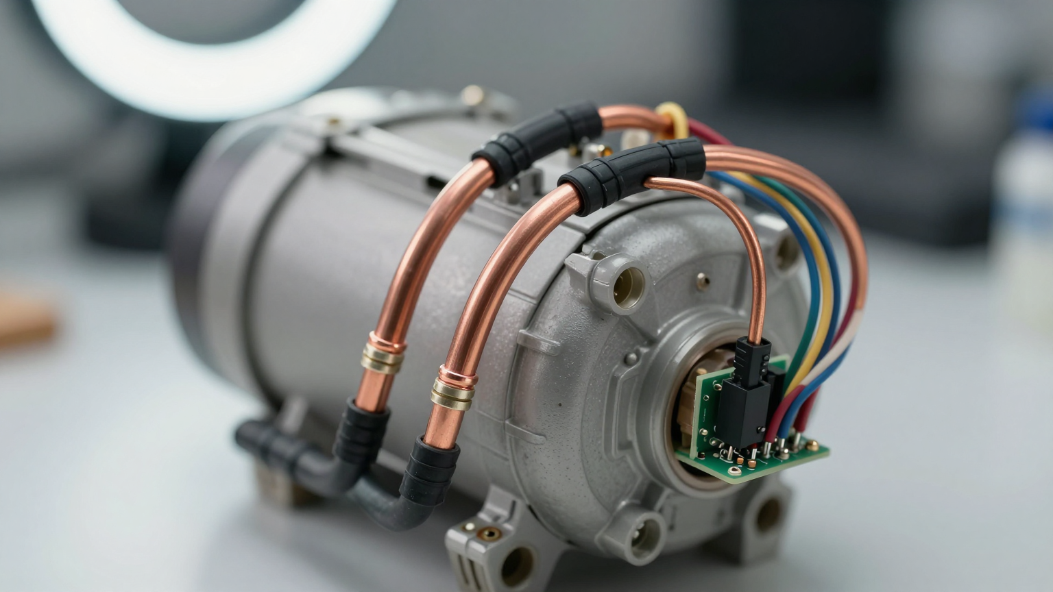
- Engineering Resolution: Implement an active cooling system, like a miniature DC compressor, that circulates and dehumidifies the internal air. As the air passes over the cold evaporator, moisture condenses out and is captured, actively lowering the dew point of the entire internal volume.
- Integration Trade-off: This moves from a simple passive component to a subsystem with mechanical parts, refrigerant lines (using R134a), and control logic. However, it replaces an unreliable solution with a robust, active one.
Gate 2: The Internal Heat Load Exceeds Passive/TEC Capabilities
- Constraint: Internal components like motors, processors, or even the diagnostic process itself generate a significant or variable amount of heat (e.g., loads ranging from 30W to 550W).
- Decision Trigger: A Thermoelectric Cooler (TEC) cannot maintain the target temperature without an unacceptably large heat sink, or its performance collapses as ambient temperatures rise toward 50°C. The TEC’s low Coefficient of Performance (COP) results in excessive waste heat and power consumption.
- Engineering Resolution: A variable-speed miniature DC compressor offers a significantly higher COP. It can dynamically adjust its output to precisely match the heat load, maintaining tight temperature stability (±0.1°C) without the inefficiency of on/off cycling.
- Integration Trade-off: A compressor system requires a more sophisticated control scheme (typically a PID loop) to manage its variable speed. It also introduces low-level vibration that must be mitigated.
Gate 3: Temperature Stability and Ambient Immunity are Critical
- Constraint: The diagnostic assay or stored reagents require stringent temperature stability that cannot be compromised by fluctuations in the external lab environment.
- Decision Trigger: The system fails validation when tested at the extremes of its specified operating range (e.g., 10°C to 50°C ambient). TECs, whose cooling capacity is directly tied to the temperature differential (ΔT), often struggle to perform at the higher end of this range.
- Engineering Resolution: A vapor compression cycle is a closed-loop system that is far more resilient to changes in ambient temperature. It can reliably deliver its rated cooling capacity and maintain stability of ±0.1°C even when the external environment is challenging.
- Integration Trade-off: While modern miniature compressors are quiet (often operating below 45 dBA), they are not silent like a TEC. This requires careful mechanical integration and vibration damping (e.g., rubber grommets) to ensure acoustic noise doesn’t interfere with sensitive measurements.
Integration Notes for Miniature DC Compressors
Integrating a compressor is not a simple drop-in replacement. It requires a holistic approach to system design. These notes are based on common engineering considerations we encounter.
Mechanical
- Enclosure Sealing: This cannot be overstated. The effectiveness of an active system relies on creating a closed-loop microclimate. Every joint, pass-through, and seal must be considered part of the thermal system.
- Vibration and Noise: The compressor unit (weighing between 450g and 780g) should be mounted with vibration-damping grommets. Position it away from acoustically or vibration-sensitive components like imaging sensors or microfluidic pumps.
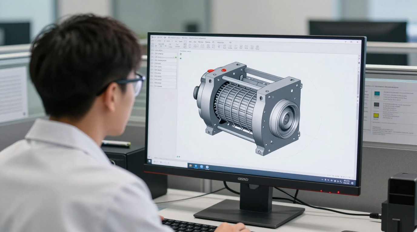
- Component Layout: Unlike a monolithic TEC, a compressor system’s components (compressor, condenser, evaporator, expansion valve) can be distributed. This offers design flexibility but requires careful planning of refrigerant line routes to avoid sharp bends or kinks.
Electrical
- Power Supply: These systems run on low-voltage DC (typically 12V, 24V, or 48V). The power supply must be rated to handle the compressor’s inrush current on startup, which can be higher than its steady-state draw.
- Control Logic: The variable-speed driver board must be integrated with your instrument’s main controller. It will require a temperature sensor input and a control signal (often PWM or serial) to modulate compressor speed based on the real-time thermal load.
Thermal
- Condenser Airflow: The condenser is where heat is rejected to the ambient environment. It must have an unobstructed source of airflow. Starving the condenser is one of the most common causes of poor cooling performance.
- Insulation: Insulate the evaporator and the cold-side refrigerant lines. You want to deliver cooling only to the target zone, not have it lost to the surrounding air inside the enclosure.
- The Microclimate Principle: The goal is to cool and dehumidify the trapped volume of air. This is the core principle of active condensation prevention. By continuously circulating the internal air over an evaporator, you actively lower its dew point, ensuring all other surfaces in the chamber remain dry.
Frequently Asked Questions (FAQ)
Why not just use a more powerful Thermoelectric Cooler (TEC)?
A TEC’s efficiency (COP) drops significantly as the temperature difference between the hot and cold sides increases. In warm ambient conditions, a TEC will consume much more power and generate more waste heat to achieve the same amount of cooling as a miniature compressor. This extra waste heat can add to the overall thermal burden of your system.
Our instrument has very limited space. Isn’t a compressor system too bulky?
Miniature DC compressors are surprisingly compact, with weights starting around 450 grams. More importantly, the system is distributed: the small compressor, condenser, and evaporator can be placed in different locations, offering greater layout flexibility than a large, monolithic TEC with its required heatsink.
How does a compressor prevent condensation if it’s making things colder?
It works by creating a controlled microclimate. The system seals the chamber, then cools and circulates the internal air. As air cools, it drops its moisture onto the evaporator coil. This process actively dehumidifies the air, drastically lowering its dew point. The goal is to keep critical surfaces above the internal dew point.
We need near-silent operation. Is a compressor viable?
While not perfectly silent like a solid-state TEC, modern rotary compressors are exceptionally quiet, with operating levels often below 45 dBA. With proper mounting and vibration isolation, they are successfully used in many noise-sensitive medical and laboratory devices.
Our device must operate in labs that can reach 50°C. Can this system handle that?
Yes. Vapor compression systems are designed to perform well in high ambient temperatures, up to 50°C. This is a key advantage over TECs, which struggle to maintain a large temperature differential in such conditions.
Do we need to be HVAC experts to integrate this?
No. These are self-contained, pre-charged systems. The engineering challenge is not in refrigerant handling but in the mechanical, electrical, and thermal integration—mounting the components, providing clean DC power, and implementing the control loop.
Conclusion: Shifting from Passive Failsafes to Active Control
The journey of troubleshooting condensation often begins with passive solutions like better seals and more insulation. These are fundamental to good thermal design. However, for high-performance IVD instruments with dynamic thermal loads, challenging ambient environments, or frequent user interaction, a point is reached where passive methods are no longer reliable.
When your system crosses that threshold, active management becomes necessary. Answering the question of how to prevent condensation in IVD cooling systems often leads to a miniature DC compressor. It provides the cooling power, efficiency, and stability to create a controlled microclimate, actively managing both temperature and humidity. This approach is best suited for applications where performance and reliability justify the added integration complexity over simpler, but less capable, cooling technologies.
If your project is facing these challenges, exploring the specifications of a robust cooling solution may be the next step. You can find more details on our miniature DC compressor systems and their performance envelopes.


0 条评论