Field Snapshot: Investigating Vibration Mounting Effects on Mini Compressor Performance
We recently consulted on a project involving a portable medical cooler. The unit performed flawlessly during bench testing but began showing inconsistent cooling performance and a new, high-pitched whine after being deployed in service vehicles. The OEM was concerned about a potential component failure, but the root cause was subtler. The investigation quickly revealed that the combination of transport vibration and the chosen mounting method was at the heart of the problem. This field note details the diagnostic checks we performed, the decision gates that guide mounting strategy, and the critical integration trade-offs that are often overlooked.
By the end of this post, you will have a practical framework for selecting a mounting and isolation strategy that preserves the performance and reliability of your compact DC cooling system, especially in mobile or vibration-prone applications.
First Checks: Initial Diagnostics for Performance Loss
When a compressor’s performance degrades after transport or installation, we start with the fundamentals of its physical integration. These checks can often identify the issue without needing to break into the sealed refrigerant system.
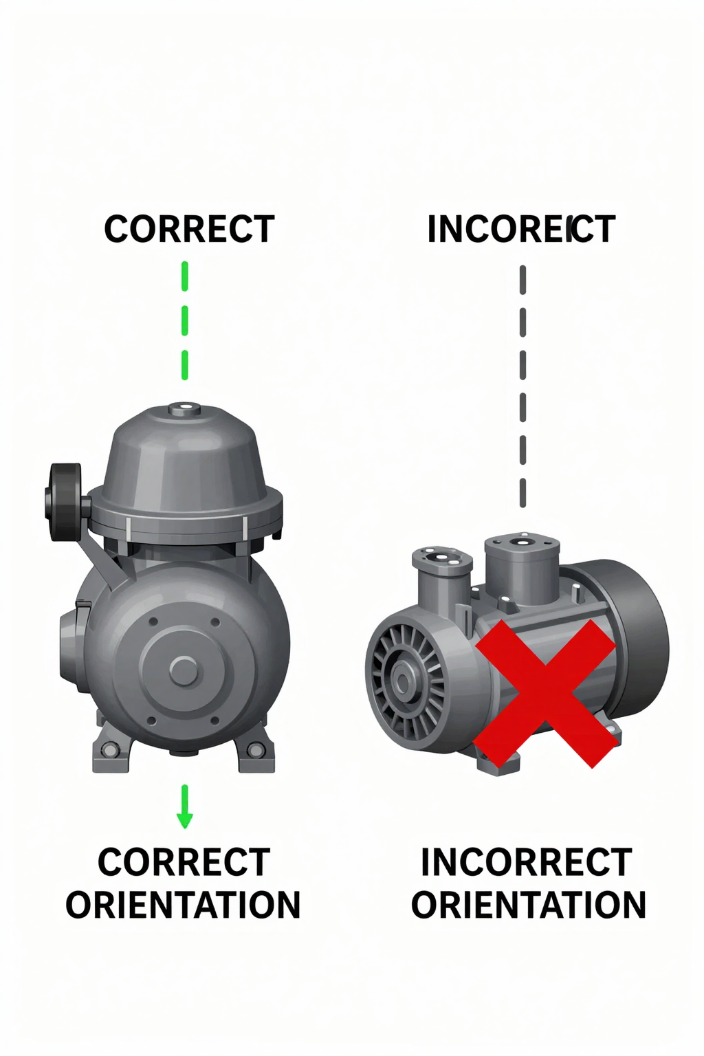
- Check: Compressor Orientation.
Why: The compressor’s oil management system is gravity-fed. It is designed to operate in a vertical, dome-up position.
What it suggests: If the unit has been installed or shifted to an angle exceeding its operational tilt limit of ±15°, oil cannot return to the sump properly. This starves the mechanism of lubrication, increasing friction, noise, and leading to a rapid decline in cooling capacity and eventual seizure. - Check: Mounting Grommet Condition.
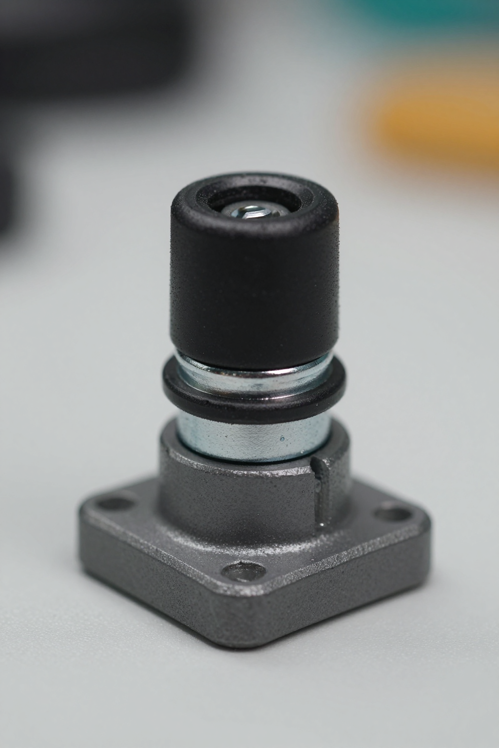
Why: The supplied rubber grommets are the primary vibration isolators. Their effectiveness depends on correct compression.
What it suggests: Over-tightened fasteners can crush the grommets, turning them into hard spacers that transmit, rather than absorb, vibration. Conversely, loose fasteners allow the compressor to rattle. Hardened or cracked grommets from age or heat exposure also fail to provide adequate damping. - Check: Refrigerant Line Strain and Contact.
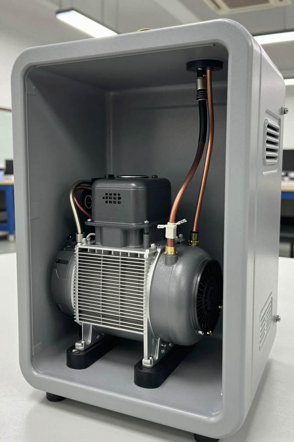
Why: The mounting system is easily defeated if rigid refrigerant lines create a secondary path for vibration.
What it suggests: If copper lines are rigidly fixed to both the compressor and the chassis without flexible sections, they transmit vibration directly, bypassing the isolators. We also check for any points where the lines or compressor shell might be making intermittent contact with the enclosure, which can cause unexpected noises.
Common Failure Modes & System Constraints
Understanding how mounting issues manifest as specific symptoms helps accelerate troubleshooting. The vibration mounting effects on mini compressor systems are not always obvious, but they follow predictable patterns.
- Symptom: A new, high-frequency whine during operation.
Likely Cause: Hard-mounting or compressed grommets are allowing the compressor’s operational frequency to resonate with the system chassis.
Why it matters: This indicates high-stress vibration is being transmitted throughout the system, which can fatigue solder joints, electrical connections, and the compressor’s internal components. - Symptom: Gradual but permanent loss of cooling power.
Likely Cause: Chronic operation outside the specified ±15° vertical tilt angle.
Why it matters: This points to accelerated wear due to insufficient lubrication. The damage is often cumulative and irreversible without replacing the compressor. - Symptom: A distinct rattling or knocking sound, especially at startup.
Likely Cause: The vibration isolators are bottoming out, or the mounting hardware is loose.
Why it matters: This creates shock loads that are far more damaging than steady vibration. It also suggests a risk of the fasteners backing out completely over time. - Symptom: Oil residue or staining near the compressor’s brazed joints.
Likely Cause: Unmitigated vibration is fatiguing the refrigerant line connections.
Why it matters: This is a primary indicator of an imminent refrigerant leak, which will lead to a total loss of cooling.
Decision Gates for Mounting and Isolation Strategy
Choosing the right mounting strategy involves a series of decisions based on the application’s specific constraints. Moving through these gates helps avoid costly redesigns later in the development cycle.
Gate 1: Vibration Environment Profile
- Constraint: The system will be deployed in a known high-vibration environment (e.g., vehicle, drone, industrial equipment).
- Decision Trigger: The vibration profile involves frequencies or amplitudes that standard rubber grommets cannot effectively dampen.
- Engineering Resolution: Specify engineered isolators, such as silicone or wire rope mounts, that are tuned to the application’s specific vibration spectrum.
- Integration Trade-off: This approach increases BOM cost and typically requires a larger physical footprint for the mounting hardware. It also necessitates sourcing vibration data for the target environment to make an informed selection.
Gate 2: Compressor Orientation Constraint
- Constraint: The industrial design or enclosure layout makes a vertical compressor orientation difficult.
- Decision Trigger: The required mounting angle for the compressor exceeds the ±15° vertical limit.
- Engineering Resolution: This is a firm constraint. The resolution is almost always a redesign of the system layout to accommodate the vertical orientation. Operating outside this range is not a viable long-term option.
- Integration Trade-off: The trade-off is between changing the mechanical layout versus accepting severely reduced component life and unpredictable performance. In nearly all cases, adjusting the layout is the correct engineering choice.
Gate 3: Acoustic Noise Requirements
- Constraint: The end product has a strict acoustic noise limit, measured in dB(A), such as in a medical or laboratory device.
- Decision Trigger: Baseline testing with standard mounting shows that structure-borne noise is pushing the system over its acoustic budget.
- Engineering Resolution: Implement a “soft mount” strategy using lower-durometer grommets to maximize isolation. Ensure refrigerant lines are fully decoupled with flexible sections and that no other components can create a vibration bridge.
- Integration Trade-off: Softer mounts allow for more physical displacement of the compressor. This requires designing in a larger clearance zone around the unit to prevent it from contacting the enclosure during operation or transport.
Integration Notes: Mechanical, Electrical, and Thermal
Beyond the core mounting strategy, successful integration requires attention to detail in surrounding systems.
- Mechanical: Always use the provided metal sleeves inside the grommets. They are designed to act as a stop, preventing over-compression of the rubber. Ensure there is adequate clearance around the entire compressor to account for movement on its mounts.
- Electrical: Use high-strand-count, flexible wiring for all connections to the compressor. This prevents work-hardening and eventual breakage from constant, small movements. Secure wire harnesses to the chassis, leaving a small service loop to absorb vibration without stressing the terminals.
- Thermal: Ensure that the mounting hardware and any added acoustic shielding do not obstruct airflow over the compressor shell. The shell is a critical surface for heat dissipation, and blocking it can cause the unit to overheat and trip its thermal protector.
- Maintenance: In systems that require periodic service, make the inspection of mounting hardware a checklist item. Check for grommet degradation (cracking, hardening) and verify the torque on mounting fasteners, as vibration can cause them to loosen over time.
Frequently Asked Questions (FAQ)
Can I mount the compressor horizontally to fit it into a tight enclosure?
This is not recommended. The compressor is designed for a vertical orientation (±15°) to ensure proper oil circulation. Horizontal operation will lead to lubrication failure and a significantly shortened service life.
What happens if the mounting grommets are tightened too much?
Over-tightening compresses the grommets and removes their ability to absorb vibration. They effectively become hard spacers, transmitting noise and vibration directly to the chassis, which can cause the issues described in this note.
Why would cooling performance drop after shipping the unit?
This is a classic symptom of a mounting issue. A hard jolt during shipping could have caused an improperly secured compressor to shift, or the sustained vibration of transport may have damaged a component that was already stressed by a poor mounting setup.
Is a louder compressor always a sign of a mounting problem?
Not always, but it is a primary diagnostic indicator. Before investigating the sealed refrigerant system, ruling out structure-borne noise from a mounting issue is a critical first step. The vibration mounting effects on mini compressor noise are significant.
Can I hard-mount the compressor for maximum stability in a mobile unit?
Hard-mounting is strongly discouraged. It provides a direct path for both internal compressor vibration to exit and external road or transport vibration to enter, stressing all components and creating significant noise.
What’s more important: orientation or vibration isolation?
Both are critical, but orientation is a non-negotiable design constraint. An incorrectly oriented compressor will fail, regardless of how well it is isolated. Proper isolation is essential for reliability and acoustic performance once the orientation requirement is met.

Conclusion: Mounting as a System-Critical Decision
Treating the mounting system as an afterthought is a common cause of field failures in otherwise well-designed compact cooling systems. The vibration mounting effects on mini compressor performance, noise, and long-term reliability are too significant to ignore. The compressor’s vertical orientation is a firm constraint driven by its internal design. From there, the choice of isolation hardware should be a deliberate engineering decision based on the application’s environment, acoustic targets, and service life requirements.
For systems operating in benign, stationary environments, the standard supplied hardware is often sufficient. For any mobile, noise-sensitive, or high-reliability application, designing a robust isolation strategy is a core part of the integration process. For detailed specifications on our compact cooling solutions, see the 12V Mini Compressor product page.


0 条评论