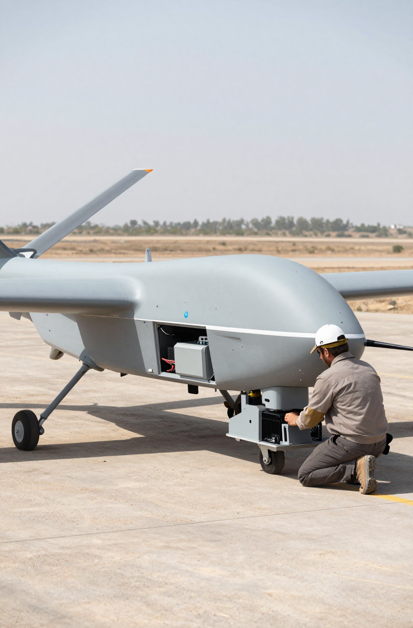
The mission brief is straightforward: get the UAV airborne and begin collecting sensor data immediately. But on the engineering side, a common and frustrating problem emerges. The aircraft takes off after sitting on a hot tarmac, but for the first ten minutes of flight, the sensitive optical payload remains thermally unstable. Its temperature won’t pull down, calibration drifts, and the initial data is unusable. This scenario, where a cooling system fails to overcome ground-based heat soak, points to a handful of common integration issues. This is not a failure of the hardware, but often a failure in the system’s thermal, electrical, or aerodynamic design.
This field note walks through our diagnostic process for troubleshooting these exact symptoms. By the end, you’ll be able to identify the likely constraints in your system and understand the decision gates that lead to a stable, high-performance thermal solution using a miniature dc compressor for rapid cooldown.
Field Snapshot: Why Won’t My UAV Payload Cool Down After Takeoff?
We were recently on-site with a client whose aerial surveillance platform faced this exact issue. The payload bay, equipped with a compact refrigeration system, was designed to keep a high-power sensor suite stable. Despite the system running, the temperature inside the bay would hover stubbornly high for the critical initial phase of the flight, long after the ambient air at altitude was cool. The core problem wasn’t capacity; it was an inability to shed the heat absorbed on the ground fast enough. This guide outlines the checks we performed, the failure modes we commonly find, and the engineering trade-offs that resolve them.
First Checks: What We Look at On-Site
Before diving into component swaps or complex data logging, we start with three physical checks. These often reveal over 80% of performance issues in UAV integrations.
- Check: The airflow path for the condenser exhaust. We use a smoke pencil or thermal camera to visualize where the hot air is going.
- Why: Recirculating hot exhaust air back into the cooling system’s intake is the single most common cause of performance degradation. The system is forced to cool the air it just heated, fighting a losing battle.
- What it suggests: If exhaust air is not positively ducted away from the aircraft’s fuselage and any system intakes, the aerodynamic and thermal layout needs revision.
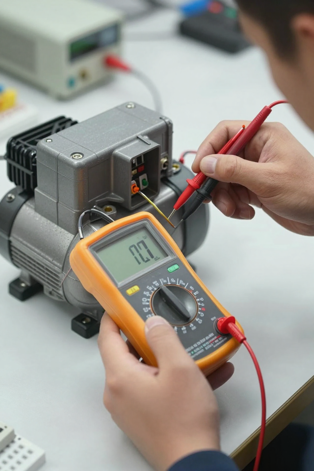
- Check: System voltage at the compressor’s terminals during a full-power cooldown cycle. We measure this while other high-draw systems, like servos or transponders, are active.
- Why: The compressor requires a stable 12V DC source and can draw up to 180W during its high-speed ramp-up. Transient voltage drops from other components can starve the compressor controller, forcing a protective shutdown or preventing it from reaching its maximum speed of 4500 RPM.
- What it suggests: The power budget is too tight, the wiring gauge is insufficient for the current draw, or the power distribution board cannot supply stable voltage under peak load.
- Check: The physical placement of the thermal sensor inside the cooled payload bay.
- Why: The compressor’s variable-speed driver uses this sensor to regulate its speed. If the sensor is in a dead-air pocket, too close to the cold evaporator coil, or near an unexpected heat source, the control logic gets a false reading and cannot manage the thermal load efficiently.
- What it suggests: The control loop is effectively blind, running the compressor too slow or too fast, and never achieving thermal stability.
Common Failure Modes in Compact Integrations
When the first checks don’t yield a clear answer, we look for specific symptoms that point to deeper integration problems. In the tight confines of a UAV, these issues are common.
- Symptom: Cooldown is extremely slow, far exceeding the expected 5-10 minute window.
- Likely Cause: This is the classic sign of condenser air recirculation or operating in ambient temperatures above the system’s 55°C rating. It can also be caused by significant air leaks into the “sealed” payload bay.
- Why It Matters: The system simply cannot reject heat to the outside environment faster than it’s being generated or leaking in.
- Symptom: The compressor audibly cycles on and off or fails to start consistently.
- Likely Cause: This is almost always an electrical issue. The controller’s under-voltage protection is likely being triggered. Check the power supply for sags when other UAV systems activate.
- Why It Matters: This points to a systemic power distribution problem, not a fault with the cooling unit itself. The entire aircraft’s power budget may need to be re-evaluated.
- Symptom: The system draws significantly more than 180W of power.
- Likely Cause: A blocked condenser coil. Debris from a dusty takeoff environment or an obstructed exhaust path forces the compressor to work against excessively high head pressure.
- Why It Matters: This is inefficient, puts unnecessary stress on the compressor, and can lead to premature failure.
- Symptom: A layer of frost or ice forms on the evaporator coil inside the payload bay.
- Likely Cause: Insufficient airflow across the evaporator. This is common when internal payload components are packed too tightly, blocking airflow paths.
- Why It Matters: A frosted coil is an insulator, not a heat exchanger. It chokes the system’s ability to absorb heat from the payload bay, crippling performance.
Decision Gates for Active Thermal Management
Many teams arrive at a miniature dc compressor for rapid cooldown after other methods have proven insufficient. These decision gates clarify why and when that transition is necessary.
Gate 1: Cooling Below Ambient Temperature
- Constraint: The payload’s electronics must be held at a stable temperature (e.g., 25°C) even when the aircraft is on a 45°C tarmac or flying through warm air.
- Decision Trigger: Forced air cooling with fans is no longer viable. Fans can only approach ambient temperature; they can never cool below it.
- Engineering Resolution: Implement an active refrigeration system. A vapor-compression cycle physically moves heat from the payload to the outside air, creating a significant temperature differential.
- Integration Trade-Off: This adds the compressor’s weight (0.68 kg) and power draw to the aircraft’s budget, which may impact flight endurance or payload capacity. It’s a necessary trade-off for thermal stability.
Gate 2: Managing High Thermal Loads
- Constraint: The total heat load from processors, sensors, and solar gain exceeds 100W.
- Decision Trigger: Thermoelectric coolers (TECs) become highly inefficient at these loads. Their low Coefficient of Performance means they draw an excessive amount of power for the cooling they provide, making them unsuitable for power-sensitive UAVs.
- Engineering Resolution: A miniature dc compressor for rapid cooldown provides a much higher CoP, capable of removing up to 450W of heat while drawing only 180W of power.
- Integration Trade-Off: This introduces a mechanical system with moving parts, which requires more careful integration regarding vibration compared to a solid-state TEC.
Gate 3: Requirement for Rapid Cooldown
- Constraint: The mission requires the payload to be thermally stable and calibrated within 5-10 minutes of takeoff.
- Decision Trigger: Passive solutions (heat sinks) or undersized active systems cannot remove the stored thermal energy from ground heat soak quickly enough.
- Engineering Resolution: Use a system designed for high-throughput heat removal. A variable-speed compressor can operate at a high speed (up to 4500 RPM) to quickly pull down the initial temperature, then throttle back to a lower speed (e.g., 2000 RPM) to maintain it efficiently.
- Integration Trade-Off: The electrical system must be designed to handle the peak power draw during this initial cooldown phase without voltage sags that could affect other avionics.
Integration Field Notes
Successful integration goes beyond the spec sheet. These are non-negotiable considerations we’ve learned from field deployments.
- Mechanical:
- Always use vibration dampeners to mount the compressor, especially if it’s near optical payloads or IMUs. While vibration is low, direct mounting is not a recommended practice.
- Ensure there is service access to the condenser and evaporator coils. In dusty or maritime environments, they will need periodic cleaning to maintain performance.
- The compressor housing is not a structural element. Do not use it as a mounting point for other hardware.
- Electrical:
- Run a dedicated, heavy-gauge wire pair directly from a stable power source to the compressor controller. This is the best way to minimize voltage drop.
- Confirm your power supply or battery management system can handle the 180W peak draw without instability.
- Route power lines separately from sensitive data or signal wires to avoid any potential for EMI.
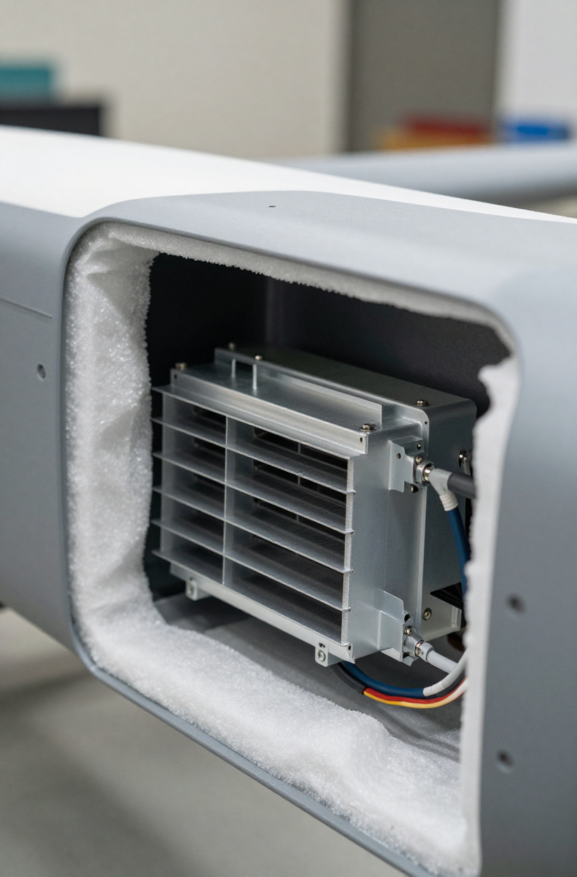
- Thermal:
- Seal the cooled enclosure. Air leaks from the outside are a direct thermal load and dramatically reduce performance and efficiency.
- The condenser’s hot air exhaust must be ducted so that it cannot, under any flight condition, be ingested by the evaporator’s air intake. This is the most critical layout constraint.
- Insulate the walls of the payload bay. This reduces the passive thermal load from the sun and ambient air, allowing the compressor to focus on removing heat from the electronics.
Frequently Asked Questions from the Field
Why can’t we just use a more powerful fan?
A fan can only move air around; it cannot cool that air below the ambient temperature. If your payload needs to be 25°C while the outside air is 40°C, a fan is not a viable solution.
The compressor seems to shut down when we actuate our landing gear. What’s happening?
This strongly suggests a transient voltage drop. The high current draw from the landing gear motors is likely pulling the system voltage below the compressor controller’s minimum threshold, causing a protective shutdown. You need to analyze your power distribution and possibly use heavier gauge wiring.
How critical is the separation between the hot and cold side airflow?
It is the single most important factor for performance. Even a small amount of hot air recirculation will force the system to work harder, draw more power, and fail to reach its target temperature.
Can we mount the compressor directly to our sensor’s mounting plate to save space?
This is not recommended. While the compressor is well-balanced, it’s still a mechanical device. Use vibration-damping mounts to isolate it from any sensitive optical or inertial sensors.
Our cooldown time is 15 minutes, not the 5-10 you’ve mentioned. What’s the first thing to check?
First, verify with a smoke pencil that you have zero hot air recirculation. Second, measure the voltage at the unit’s terminals during startup to ensure it’s not sagging. These two issues account for the vast majority of slow cooldown problems.
Does the compressor run at full speed all the time?
No, it is a variable-speed system. It typically runs at a high RPM (up to 4500 RPM) to handle the initial heat soak, then ramps down to a more efficient, quieter speed (2000 RPM or higher, as needed) to maintain the target temperature.
Conclusion: When Active Cooling is the Right Call
While passive and thermoelectric solutions have their place, they fall short when the operational environment is challenging and performance is critical. If your application involves high ambient temperatures, significant internal heat loads (above 100W), and a mission-critical need for rapid cooldown after ground soak, then a direct-expansion, active thermal management system is the most robust engineering path.
The key is not just selecting the right component, but integrating it correctly. By paying close attention to airflow management, power stability, and thermal insulation, you can eliminate the frustrating troubleshooting cycles and achieve consistent, reliable payload performance from the moment your UAV leaves the ground. For systems facing these constraints, a purpose-built 12V mini compressor is often the most direct engineering solution.


0 条评论