The EO/IR sensor data is drifting again. The aircraft is operating at high altitude where the thin air offers little convective cooling, and solar gain is significant. The passive heat sink and even the existing thermoelectric cooler (TEC) on the gimbal payload can’t maintain the focal plane array’s required stable temperature. The result is thermal noise, image artifacts, and compromised mission data. Complicating matters, the payload bay has almost no spare volume or weight capacity, and the entire system is subject to constant, high-frequency vibration. This is a common scenario where passive solutions hit their physical limits, forcing a move to active refrigeration. By the end of this post, you’ll be able to determine the key decision gates for specifying and integrating a miniature vapor compression system for your application.
Field Snapshot: When to Specify a UAV Sensor Cooling Miniature Compressor
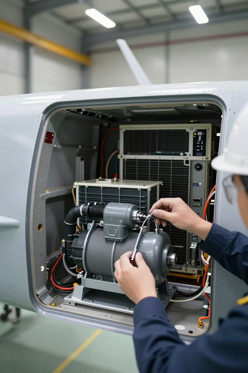
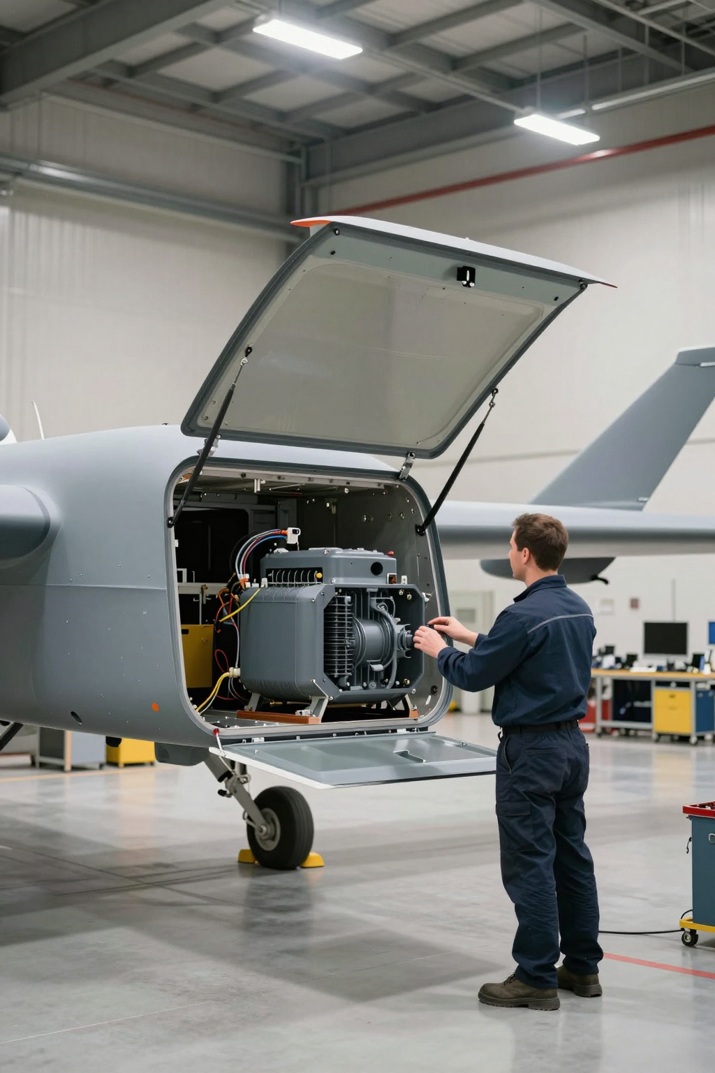
We were recently on-site with a client integrating a high-resolution surveillance pod onto a medium-altitude, long-endurance UAV. Their primary challenge was thermal stability. The sensor’s performance degraded significantly once the ambient air temperature exceeded a certain threshold, a frequent occurrence during daytime operations. Their existing TEC-based solution was drawing too much power for the cooling it provided, and its large heat sink was creating mechanical integration problems. The core issue was a high thermal load in a confined space, compounded by the environmental challenges of altitude and vibration. This is the precise point where a UAV sensor cooling miniature compressor enters the conversation—not as a simple component swap, but as a system-level architectural decision.
First Pass: The 3 Initial Engineering Checks
Before diving into a complete system redesign, our first step on any project is to validate the core constraints. In a situation like this, we start with a few fundamental checks to confirm the nature of the thermal problem.
- Check Thermal Delta & Heat Load: We first analyze the temperature difference (Delta T) between the required sensor case temperature and the ambient temperature inside the payload bay. We also quantify the total heat load, which includes the sensor’s own dissipated power plus any parasitic heat leak from the surroundings. Why: This tells us if passive or thermoelectric cooling is even theoretically viable. If the required temperature is near or below the ambient air temperature, or if the heat load is substantial, a TEC’s efficiency (Coefficient of Performance, or COP) drops dramatically, making it an impractical choice. What it suggests: A small Delta T or a high heat load (typically over 50-60W for compact systems) strongly indicates the need for a more efficient cooling technology, like vapor compression.
- Check Power Budget & Quality: We review the UAV’s power distribution bus. Is there a stable, clean DC voltage source available? How much current can be allocated to the thermal management system without affecting avionics or primary mission systems? Why: A miniature compressor, while efficient, has a startup inrush current and requires a dedicated controller. Unstable or noisy power can lead to performance issues or premature failure. What it suggests: A constrained power budget might favor a variable-speed compressor that can modulate its power draw to match the real-time thermal load, running at a lower RPM (like 2000 RPM) during low-load phases and ramping up only when needed. The system must be able to supply between 30W and 130W of continuous power.
- Check Mechanical Envelope & Vibration Profile: We get the CAD models for the payload bay and the vibration analysis data for the airframe. Where can components physically fit? What are the dominant vibration frequencies and g-forces during different phases of flight? Why: Unlike a solid-state TEC, a compressor has moving parts. While designed for mobile use, its reliability and acoustic signature depend heavily on proper mechanical isolation. What it suggests: The physical layout may demand a split system, where the compressor and condenser are located separately from the evaporator (the cold plate). The vibration data dictates the specifications for the required damping mounts.
Common Failure Modes & Environmental Constraints
When troubleshooting EO/IR systems in the field, symptoms often point back to thermal instability. Understanding these failure paths helps clarify why a more robust solution like a UAV sensor cooling miniature compressor becomes necessary.
- Symptom: Increased noise or “dead pixels” in the imagery. Likely Cause: The sensor’s focal plane array (FPA) temperature is too high. Most high-performance sensors have a narrow optimal temperature window for clean operation. Why it matters: This is a direct failure to meet the primary mission requirement. The data being collected is corrupted and may be unusable.
- Symptom: The cooling system works on the ground but fails at altitude. Likely Cause: The hot-side heat sink (for a TEC or condenser for a compressor) is failing to reject heat effectively in thin air. Air density decreases with altitude, severely reducing the efficiency of passive or fan-forced convection. Why it matters: The entire thermal management system’s performance is tied to its ability to dump waste heat into the environment. A system not designed for high-altitude operation will inevitably fail.
- Symptom: Intermittent system shutdowns or performance dips. Likely Cause: Voltage sag on the power bus. The cooling system’s peak power draw, especially during startup or high thermal loads, is pulling the bus voltage below the operating threshold for other electronics. Why it matters: This creates a cascading failure risk that can compromise the entire aircraft, not just the payload.
- Symptom: TEC performance degrades over time. Likely Cause: Thermoelectric modules are sensitive to thermal cycling. Repeated expansion and contraction can lead to micro-fractures and a gradual loss of cooling capacity. Why it matters: A system that passes initial testing may still fail prematurely in the field, leading to costly repairs and mission downtime.
- Symptom: Cracks in solder joints or component leads on the controller board. Likely Cause: Unmitigated, high-frequency vibration from the airframe is being transferred directly to the electronics. Why it matters: This is a classic mechanical integration failure. Without proper vibration damping, even ruggedized components will eventually fail from fatigue.
Decision Gates for Active Refrigeration
Moving to a miniature vapor compression system is a significant step. Here are the engineering decision gates that typically force the transition.
Gate 1: The Sub-Ambient Cooling Requirement
- Constraint: The sensor must be maintained at a temperature below the ambient air temperature inside the aircraft.
- Decision Trigger: A passive heat sink or a standard TEC cannot, by definition, achieve a temperature below the surrounding ambient without an impossibly large form factor. They only move heat; they don’t create a “colder” environment in the way a refrigeration cycle does.
- Engineering Resolution: Implement a vapor compression cycle. This is the only technology that uses a phase-change refrigerant (like R134a) to actively pump heat from a low-temperature source (the evaporator on your sensor) to a high-temperature sink (the condenser).
- Integration Trade-Off: This introduces system complexity. You now have a compressor, condenser, evaporator, and refrigerant lines. However, it unlocks the ability to achieve stable, low temperatures regardless of the ambient environment.
Gate 2: High Heat Load or Poor COP
- Constraint: The total heat load exceeds the practical limits of a thermoelectric system, or the available power budget makes the TEC’s low efficiency untenable.
- Decision Trigger: As the temperature difference a TEC has to create increases, its Coefficient of Performance plummets. For a heat load in the 100W to 400W range, a TEC system would be excessively large and draw a prohibitive amount of power.
- Engineering Resolution: A miniature DC compressor offers a significantly higher COP. It moves more watts of heat per watt of electrical input power, making it a far more efficient solution for higher heat loads.
- Integration Trade-Off: The compressor requires a sophisticated variable-speed driver board to manage its operation (from 2000 to 6500 RPM), but this also provides the benefit of matching cooling power and energy consumption directly to the load.
Gate 3: Severe Space and Volume Constraints
- Constraint: The physical volume available for the cooling system is minimal and irregularly shaped.
- Decision Trigger: The large, bulky heat sink required for the “hot side” of a high-power TEC simply won’t fit in the allocated space.
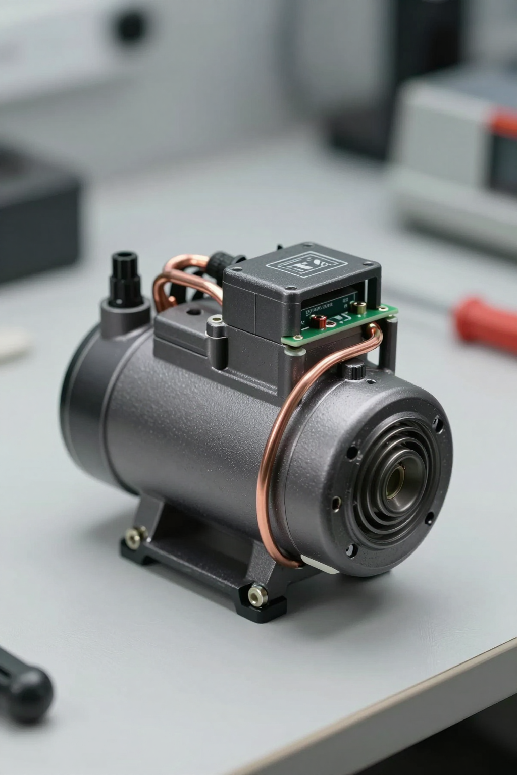
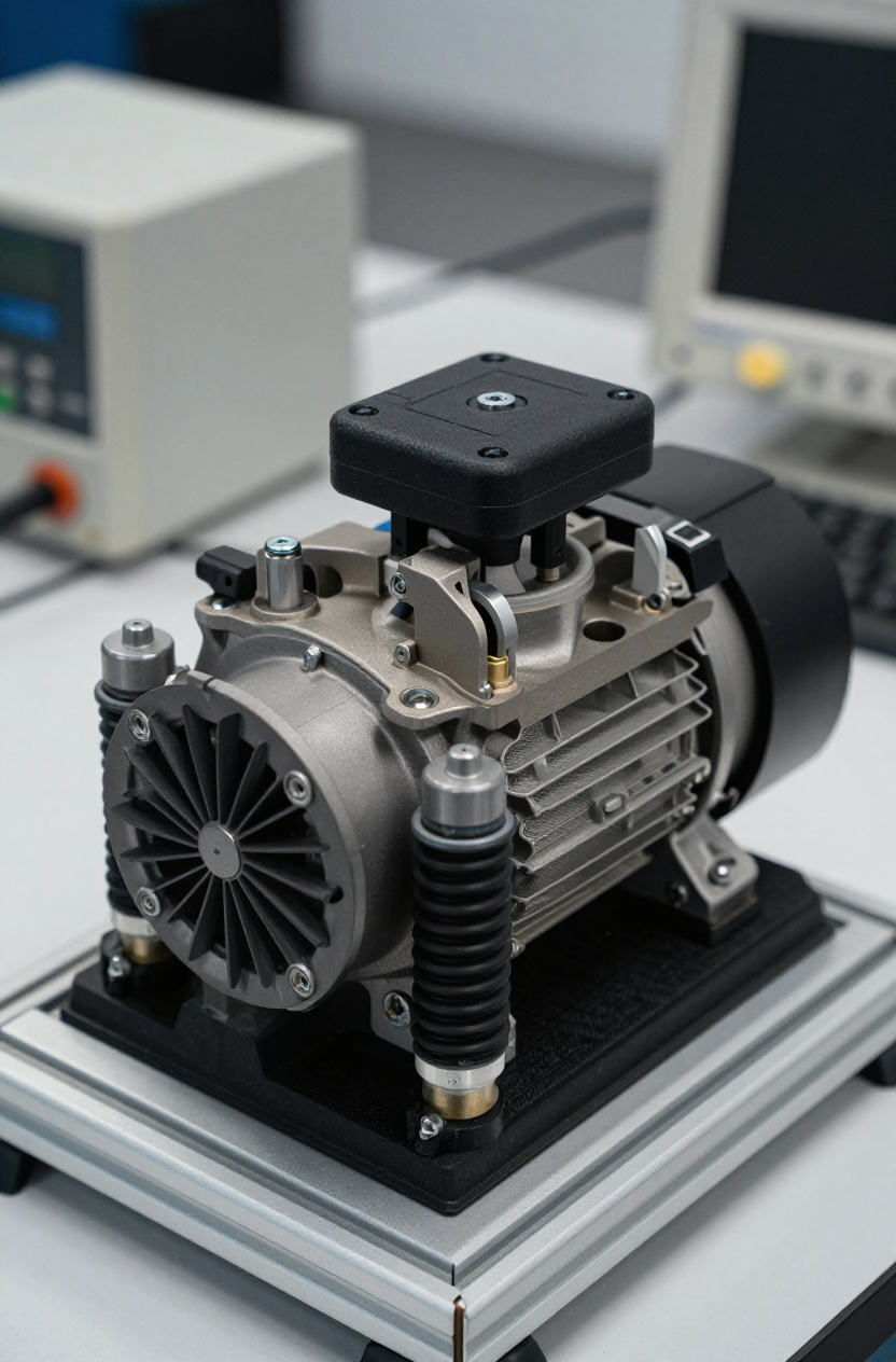
- Engineering Resolution: Use a split-system architecture enabled by a UAV sensor cooling miniature compressor. The compressor itself is very small (around 75mm in diameter and 85mm tall), and the evaporator (cold plate) can be mounted directly to the sensor, while the condenser can be placed elsewhere in the airframe where airflow is available.
- Integration Trade-Off: This requires running flexible refrigerant lines between the components, which must be carefully routed to avoid kinks and protected from vibration. However, this architectural flexibility is often the only way to integrate high-capacity cooling into a dense system.
Integration Notes: Field-Level Best Practices
This is not an installation manual, but rather a collection of field notes on what separates a successful integration from one that fails prematurely. A miniature refrigeration system is not a drop-in replacement for a fan.
- Mechanical: The compressor, weighing only 680g, must be mounted using vibration-damping grommets or a dedicated isolation plate. Never hard-mount it to the airframe. Ensure refrigerant lines have gentle bends and are secured with cushioned clamps to prevent fatigue failure.
- Electrical: The system runs on 12V or 24V DC, but the quality of that power is critical. Use twisted, shielded cables for the power supply to the driver board to minimize EMI. Ensure the power source can handle the peak current draw without significant voltage drop.
- Thermal: The thermal interface between the evaporator and the sensor’s heat spreader is paramount. Use a high-quality thermal interface material (TIM) and ensure even clamping pressure. The condenser must have a clear path for heat rejection; even if it’s just ducted air within the fuselage, it needs airflow to function.
- Maintenance: These are hermetically sealed systems, so they don’t require refrigerant top-offs. However, pre-flight inspections should include a visual check of all refrigerant lines and connections for any signs of abrasion or damage that could lead to a leak.
Frequently Asked Questions (FAQ)
How does a miniature compressor compare to a high-end TEC system?
A compressor-based system generally has a much higher Coefficient of Performance (COP), especially at larger temperature differentials. It’s more complex mechanically but is often the only viable path for cooling below ambient or managing heat loads over 50-60W in a tight power budget.
What is the actual power consumption?
It’s variable. The power draw scales with the compressor speed, which is dictated by the heat load. Expect a range from approximately 30W at minimum speed to 130W at maximum cooling capacity. This allows for intelligent power management that a simple on/off TEC system can’t offer.
Can this system handle the g-forces and vibration of a UAV?
Yes, it is designed for mobile and high-vibration environments. However, the design’s inherent robustness must be paired with a proper mechanical integration strategy, specifically the use of vibration-isolating mounts.
How does performance change with altitude?
The core refrigeration cycle is largely unaffected by the low air pressure at altitude. However, the condenser’s ability to reject heat is. The overall system design must account for lower convective heat transfer efficiency in thin air, often by using a higher-flow fan or a larger condenser surface area than would be needed at sea level.
Is the weight prohibitive for a small UAV?
The compressor itself is very light at 680g. The total system weight, including the condenser, evaporator, and tubing, needs to be calculated, but it is often comparable to or even lighter than a TEC system with its required massive heat sink for an equivalent cooling capacity.
What kind of control interface is required?
The compressor is controlled by a dedicated driver board that manages the motor. This board typically accepts a simple control signal (like PWM or serial command) to set the desired speed, making it straightforward to integrate with the aircraft’s main flight or payload controller.
Conclusion: The Right Tool for a Hard Problem
For UAV platforms where sensor performance is non-negotiable, thermal stability is a mission-critical requirement. While passive and thermoelectric solutions work well for low-power electronics in forgiving environments, they fall short when faced with high heat loads, elevated ambient temperatures, and the need for sub-ambient cooling.
A UAV sensor cooling miniature compressor represents a move to a more robust, system-level thermal solution. It’s the right engineering choice when the operational envelope demands cooling performance that other technologies cannot efficiently deliver. The integration is more involved, but the result is stable sensor temperatures and reliable data collection across a much wider range of mission profiles. If your project is hitting a thermal wall, this technology is the logical next step.
For platforms where thermal stability directly impacts mission success, direct active cooling is often the most robust path. Explore the specs for the Arctic-tek 12V Miniature Compressor to see if it fits your design envelope.


0 条评论