Angle: The critical decision is choosing between low-cost ventilation and a robust, closed-loop cooling system for remote pump station cabinets. The primary failure modes are humidity-induced corrosion of sensitive electronics and thermal shutdown of VFDs under peak load. The dominant constraint is the harsh, often corrosive and humid, ambient environment that makes open-loop air exchange a significant reliability risk.
Why Ventilation Fails: A Guide to the Micro DC Air Conditioner Pump Station Cabinet
A pump station control cabinet in a remote field location is a mission-critical asset. Inside, Variable Frequency Drives (VFDs), PLCs, and power supplies are expected to operate flawlessly for years. Yet, we consistently see premature failures—nuisance trips on hot days, corroded terminals, and complete component burnout. The common culprit is often a thermal management strategy that seemed cost-effective upfront: simple fans and filters. While ventilation has its place, in the humid, dusty, and potentially corrosive environments of water and wastewater management, it often introduces the very contaminants you need to keep out. The stakes are high, involving service interruptions, costly emergency maintenance, and shortened asset lifespan.
By the end of this technical breakdown, you will be able to determine the precise environmental and operational thresholds where shifting from ventilation to a closed-loop system becomes a necessity. We will analyze the decision-making process for integrating a compact, active cooling solution. In this article, we prioritize long-term reliability and component stability over minimal upfront cost, because the total cost of ownership for a failed control system far exceeds the initial investment in proper thermal management. A micro dc air conditioner pump station cabinet is not a luxury; it’s an engineering control for a high-failure-risk environment.
Deployment Context: Two Common Scenarios
Scenario A: The Wastewater Lift Station
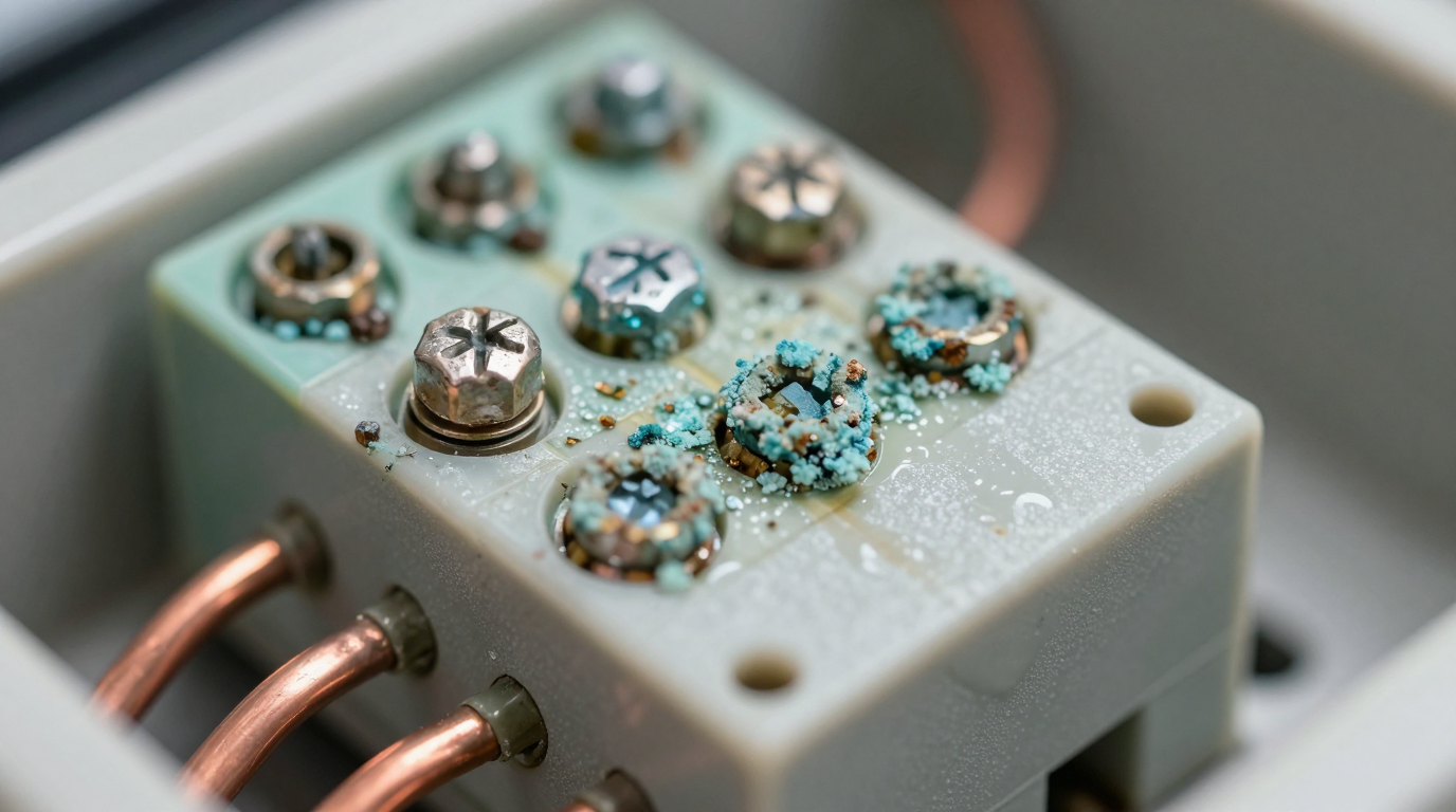
A municipal lift station houses a duplex pump control panel in a NEMA 3R enclosure, located near a coastal marsh. The original design used two filtered fans for ventilation. Within 18 months, the primary VFD began faulting on over-temperature alarms during summer afternoons. Upon inspection, the maintenance team found the fan filters clogged with pollen and saline dust. More critically, the humid, salt-laden air had caused visible corrosion on the PLC’s communication ports and power supply terminals, a classic case of water treatment cabinet humidity corrosion. The constraint here was the corrosive ambient air, which made any open-loop air exchange a direct threat to the electronics.
Scenario B: The Potable Water Booster Pump Station
A booster pump station for a new subdivision is located in a hot, arid climate. The control cabinet contains a large VFD and extensive monitoring hardware. To combat the high solar load and internal heat, the system integrator installed a powerful fan system. However, during the dry season, fine dust continuously bypassed the filters, coating heatsinks and circuit boards. This insulating layer of dust reduced the VFD’s ability to dissipate heat, forcing it to derate its output to protect itself, which in turn limited the station’s peak pumping capacity. The dominant constraint was the combination of high ambient temperatures and airborne particulate matter, which rendered the ventilation system a source of contamination rather than a cooling solution.
Failure Modes & Constraints in Pump Station Cabinets
Understanding why traditional methods fail requires ranking the risks. For a typical pump station or micro dc aircon water treatment enclosure, the threats are predictable and cascade into larger system failures.
- VFD Overheating → Nuisance Tripping → The VFD is often the largest heat source; inadequate cooling leads to protective shutdowns, interrupting service.
- Ambient Humidity Ingress → Condensation on PCBs → Morning temperature swings can cause humid air inside the cabinet to condense directly onto cool electronic surfaces, leading to short circuits.
- Corrosive Gas Ingress (H2S) → Terminal Corrosion → In wastewater applications, hydrogen sulfide and other gases drawn in by fans actively corrode copper and solder joints, causing intermittent and hard-to-diagnose faults.
- Dust & Particulate Buildup → Heatsink Insulation → Fans pull in dust that coats components, acting as an insulator and raising operating temperatures, which directly shortens component life.
- Filter Clogging & Maintenance Burden → Reduced Airflow → Fan filters require frequent cleaning; neglected filters become blocked, starving the cabinet of airflow and causing heat to build up rapidly.
- Solar Load on Cabinet → Elevated Internal Ambient → A cabinet in direct sunlight can have an internal starting temperature 15-20°C higher than the outside air, giving any cooling system a significant disadvantage from the start.
- PLC/Controller Logic Errors → Unstable Operation → Sensitive processors and memory chips are susceptible to heat-induced errors long before a full thermal shutdown occurs, leading to erratic system behavior.
- Power Supply Derating → Voltage Sags → Like VFDs, power supplies lose output capacity at higher temperatures, potentially causing voltage drops that affect connected devices.
- Compromised NEMA/IP Seal → Water & Pest Ingress → Cutting holes for fans and vents creates potential failure points in the cabinet’s environmental seal, violating its rating and allowing entry for moisture and insects.
Engineering Fundamentals: Closed-Loop vs. Open-Loop Cooling
The core of the decision rests on understanding one principle: the air path. Open-loop cooling, like a fan, uses ambient air. It pulls outside air into the cabinet, circulates it over the hot components, and exhausts it. This only works if two conditions are met: the outside air is significantly cooler than the target internal temperature, and the outside air is clean and non-corrosive. For most pump station environments, at least one of these conditions is false.
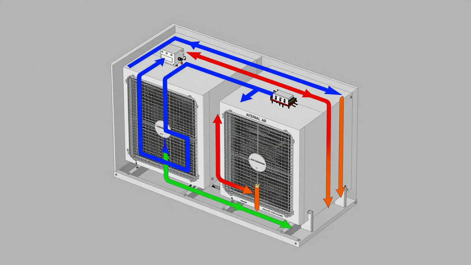
A closed-loop system, such as a micro DC air conditioner pump station cabinet, operates like a refrigerator. It creates two completely separate air circuits. The internal circuit recirculates and cools the air already inside the sealed cabinet, removing heat from the components. The external circuit uses ambient air to discharge that collected heat to the outside. There is no exchange of air between the inside and the outside. This maintains the cabinet’s seal and protects sensitive electronics from humidity, dust, and corrosive gases.
Common Misconception: “A bigger fan will solve the overheating problem.”
Correction: If the ambient air temperature is 40°C and the VFD needs to be kept below 50°C, a fan can only help if the VFD’s heat load is very small. A fan cannot cool the internal air below the ambient temperature. In fact, by pulling in 40°C air, it establishes that as the baseline. An active, refrigerant-based system like a DC enclosure air conditioner pump control panel is required to create a temperature differential, actively pumping heat out to keep the internal temperature stable and well below the ambient, regardless of the external conditions.
Key Specifications for a Micro DC Air Conditioner
When evaluating a closed-loop solution, you move from thinking about airflow (CFM) to thermal performance (Watts of cooling). The specifications are not complex, but they are critical go/no-go gates. For a micro dc aircon, the focus is on DC power compatibility, cooling capacity, and physical footprint. Below are typical parameters for our Micro DC Aircon series, which are designed for these types of compact, critical applications.
| Model (Example) | Input Voltage | Nominal Cooling Capacity | Refrigerant |
|---|---|---|---|
| DV1910E-AC (Pro) | 12V DC | 450W | R134a |
| DV1920E-AC (Pro) | 24V DC | 450W | R134a |
| DV1930E-AC (Pro) | 48V DC | 450W | R134a |
| DV3220E-AC (Pro) | 24V DC | 550W | R134a |
How to read these specs for this decision: First, match the Input Voltage to the DC power bus available in your control cabinet (typically 24V or 48V). Second, ensure the Nominal Cooling Capacity (in Watts) exceeds the total heat load generated by your internal components (VFDs, power supplies, etc.). Finally, the refrigerant type and compressor technology indicate a true vapor-compression system, capable of achieving significant cooling below ambient temperatures.
Engineering Selection Matrix: Logic Gates for Integration
An engineer must progress through a series of logic gates to justify moving from passive ventilation to an active cooling solution. This isn’t about preference; it’s about matching a solution to non-negotiable constraints.
Logic Gate 1: The Environmental Seal Gate
- Constraint Gate: Is the cabinet located in an environment with high humidity, salt fog, corrosive gases (e.g., H2S near a wastewater plant), or high levels of dust/particulates?
- Decision Trigger: If the answer is yes to any of these, any penetration of the cabinet seal for open-loop ventilation (fans/vents) introduces a high-probability path for contamination and corrosion. A NEMA 4 or 4X rating is often desired to protect the electronics, and cutting holes for fans immediately compromises this.
- Engineering Resolution: The requirement to maintain a sealed, controlled internal environment disqualifies open-loop ventilation. The path shifts to a closed-loop system, such as a gasketed heat exchanger or a micro DC air conditioner pump station cabinet, which can be mounted to the enclosure while preserving the seal.
- Integration Trade-off: This increases the upfront system cost compared to a fan. However, it eliminates the long-term operational costs of filter maintenance, component cleaning, and premature failure due to corrosion.
Logic Gate 2: The Thermal Delta Gate
- Constraint Gate: Can the internal components operate reliably at a temperature slightly above the maximum expected ambient temperature?
- Decision Trigger: If the maximum allowable internal cabinet temperature is less than or equal to the maximum external ambient temperature, a fan or heat exchanger cannot work. For example, if the VFD must be kept below 40°C for full performance, but the summer ambient temperature reaches 45°C, you must have active, refrigerant-based cooling.
- Engineering Resolution: This is the clearest indicator for an active cooling system. A Micro DC Aircon is selected because its vapor-compression cycle can actively pump heat out of the cabinet, maintaining an internal temperature that is independent of, and lower than, the outside air.
- Integration Trade-off: The system now requires a dedicated DC power budget for the air conditioner’s compressor and fans. This must be factored into the cabinet’s overall power supply sizing.
Logic Gate 3: The Heat Load Density Gate
- Constraint Gate: Is the total heat generated by the internal components (in Watts) greater than what can be passively dissipated through the cabinet’s surface area?
- Decision Trigger: A modern, compact control panel for a powerful pump can have a high density of heat-producing components (VFDs, transformers, power supplies). If the calculated internal heat load is high (e.g., over 300W in a small enclosure), natural convection and simple ventilation are insufficient, even in moderate climates, leading to pump station control cabinet overheating.
- Engineering Resolution: The cooling capacity of the selected solution must exceed the calculated internal heat load. A spec sheet is used to match the load. For example, if the total heat load is 400W, a unit with a 450W or 550W nominal capacity (like the DV1920E-AC or DV3220E-AC examples) provides a safe operating margin.
- Integration Trade-off: The physical size and mounting footprint of the cooling unit must be accommodated in the cabinet design or retrofit. This may require mechanical adjustments and careful placement to ensure proper internal air circulation.
Implementation Checklist for a Micro DC Aircon
Proper installation is as critical as proper selection. A methodical approach ensures the unit performs as expected and protects the assets within the cabinet.
-
Mechanical Installation
- Mounting Surface: Ensure the cabinet wall is flat, rigid, and strong enough to support the unit. Use the provided mounting template for precise cutouts.
- Gasket Seal: The mounting gasket is the most critical component for maintaining the cabinet’s IP/NEMA rating. Ensure the surface is clean and dry before mounting. Tighten fasteners evenly to compress the gasket without warping the flange.
- Airflow Paths: Verify that the internal cool air outlet and warm air return are not blocked by components, wiring harnesses, or DIN rails. Proper circulation is key to eliminating hot spots.
-
Electrical Connection
- Power Budget: Connect the unit to a DC power source (e.g., 24VDC or 48VDC) that can handle the compressor’s startup and running current. Use appropriately sized wiring.
- Circuit Protection: Install an appropriately rated fuse or circuit breaker on the supply line to the air conditioner, as specified in the installation manual.
- Control Wiring: If using remote alarms or controls, ensure these low-voltage signal wires are run separately from high-power cables to prevent interference.
-
Thermal Verification
- Sensor Placement: Place a temporary temperature logger near the intake of the internal air circuit (typically the warmest spot) and another near the most sensitive component (e.g., the PLC).
- Acceptance Test: After installation, run the system under a simulated full load. Verify that the internal cabinet temperature stabilizes at or below the target setpoint, even as the external ambient temperature rises.
- Condensate Management: Check that the external (hot side) condensate drain is properly routed and not blocked, preventing water from pooling.
-
Maintenance Planning
- External Coil Inspection: Periodically inspect the external heat exchanger coils for blockage from debris, leaves, or dust. Clean gently with compressed air or a soft brush to maintain efficiency.
- Fan Integrity: During inspection, confirm that both the internal and external fans are spinning freely.
- Seal Inspection: Annually check the integrity of the mounting gasket to ensure it remains pliable and fully sealed against the enclosure.

Frequently Asked Questions (FAQ)
1. Should I choose a heat exchanger or a micro DC air conditioner?
A heat exchanger is a closed-loop system, but it can only keep the internal temperature a few degrees above the external ambient temperature. If you need the inside to be cooler than the outside, or if the heat load is very high, a micro DC air conditioner pump station cabinet is the necessary choice.
2. What happens to condensation? Is it a risk?
A properly designed DC air conditioner manages condensation on the external (hot side) coil, where moisture from the ambient air condenses and is drained away from the unit. The internal (cold side) coil operates on recirculated cabinet air; as long as the cabinet was sealed in a low-humidity state, internal condensation is typically not an issue.
3. How does direct sun exposure affect performance?
Direct solar load adds a significant amount of heat to the cabinet, effectively increasing the total heat load the air conditioner must remove. If a cabinet is in full sun, it is best practice to add a solar shield (a simple raised metal cover) to create an air gap. This dramatically reduces the surface temperature and improves the efficiency of the cooling system.
4. What do I need to measure before selecting a cooling unit?
You need three key data points: 1) The total internal heat load from all components in Watts. 2) The maximum expected external ambient temperature. 3) The maximum allowable internal temperature to keep all components operating safely without derating.
5. How do I validate that the cooling system is working correctly after installation?
The best method is data logging. Use a temperature logger to record the internal cabinet temperature over a 24-48 hour period that includes the hottest part of the day and a full operational cycle of the pumps. The data should show the temperature remaining stable and below your specified maximum.
6. Can these units handle the vibration at a pump station?
Industrial-grade cooling units are designed for such environments. The use of robust BLDC rotary compressors and sturdy mechanical construction makes them suitable for the typical vibration levels found in pump stations and other industrial settings. Always check the manufacturer’s vibration and shock specifications.
7. What if my cabinet uses AC power?
While these are DC-powered units, they are frequently used in AC-powered cabinets. A simple, high-reliability AC-to-DC power supply (e.g., 24V or 48V DIN rail mount) is installed inside the cabinet to power the cooling unit. This is a common and reliable integration method.
Conclusion: The Right Tool for a Corrosive Job
The decision to move from simple ventilation to a closed-loop active cooling system is a pivot from a reactive to a proactive reliability strategy. For pump station and water treatment control cabinets, where humidity, dust, and corrosive gases are the norm, relying on open-loop airflow is a direct invitation for premature component failure. The upfront cost of a fan is low, but the lifecycle cost of service interruptions, VFD replacements, and emergency call-outs is exceptionally high.
A micro DC air conditioner pump station cabinet is the best-fit solution when the operational environment is harsh and the electronics inside are critical. It excels when you must maintain a sealed enclosure, when the internal temperature must be held below the external ambient, and when long-term, maintenance-free operation is a primary design goal. This approach is not about over-engineering; it’s about correctly matching the engineering solution to the known environmental and operational risks.
If you are designing or retrofitting control systems for harsh environments, our engineering team can help you calculate your thermal load and select the appropriate cooling solution based on your specific power constraints, enclosure geometry, and environmental challenges.


0 条评论