Field-Ready: The Ultimate Enclosure Cooling Integration Checklist for Harsh Environments
In the controlled environment of a CAD assembly, every flange aligns perfectly, and ambient air is always 20°C. In the field, however, the reality for OEM engineers and system integrators is vastly different. Enclosures warp under thermal stress, cable glands leak during heavy rain, and dust accumulation turns ventilation paths into insulation blankets. For deployments in harsh, outdoor, or mobile settings, the gap between a theoretical thermal design and a functional, long-term solution is often defined by installation quality.
This guide provides a practical, data-driven enclosure cooling integration checklist to bridge that gap. We focus on the physical and thermal realities of integrating active cooling—specifically Micro DC Aircon series and miniature DC compressors—into systems that cannot afford downtime. Whether you are cooling a remote telecom tower powered by solar or a mobile ruggedized HMI, the principles of mounting, sealing, and service access remain the critical determinants of reliability.
Deployment Context: Where Theory Meets Physics
To understand why a rigorous integration checklist is necessary, we must look at the specific constraints of off-grid and mobile applications. Standard industrial cooling often assumes unlimited AC power and regular maintenance access. Neither applies here.
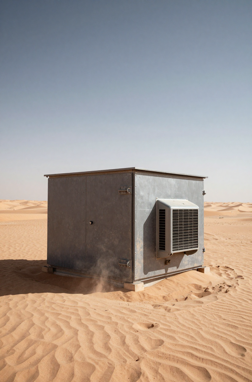
Scenario A: The Remote Solar Telecom Repeater
Consider a roadside enclosure in a high-desert environment. The ambient temperature fluctuates between 5°C at night and 45°C during the day. Solar loading adds significant heat to the cabinet skin. The power source is a 24V or 48V battery bank charged by PV arrays.
Constraints:
- Power Budget: Every watt consumed by cooling is a watt not available for the radio equipment. Efficiency is paramount.
- Maintenance Interval: The site is visited once every 6–12 months. Filter fans are disqualified due to rapid clogging.
- Thermal Load: The system requires sub-ambient cooling to keep batteries below 35°C, even when outside air is 45°C.
Scenario B: Mobile Heavy Equipment HMI
A control cabinet mounted on an autonomous agricultural vehicle.
Constraints:
- Vibration: Constant low-frequency vibration requires rigid mounting and thread-locking.
- Contaminants: The air is thick with organic dust and moisture.
- Voltage Fluctuation: The alternator provides power, but voltage spikes and dips are common during engine cranking.
Decision Matrix: Selecting the Right Thermal Strategy
Before finalizing your integration plan, validate that your cooling technology matches the environmental load. The table below compares common approaches for harsh environment deployments.
| Criteria | Filter Fans (Open Loop) | Thermoelectric (TEC/Peltier) | Micro DC Aircon (Compressor) |
|---|---|---|---|
| Sub-Ambient Cooling | Impossible (Always T_internal > T_ambient) | Yes, but limited capacity | Yes, high capacity |
| Sealing (IP/NEMA) | Low (Depends on filter media) | High (Closed Loop) | High (Closed Loop) |
| Dust/Salt Tolerance | Poor (Ingress risk) | Excellent | Excellent |
| Power Efficiency (COP) | High (but limited cooling) | Low (typically COP < 0.6) | High (typically COP > 2.0–3.0) |
| Heat Load Suitability | Low to High (if T_ambient is low) | Low (< 200W typically) | Medium to High (100W–900W+) |
| Best-Fit Scenario | Indoor, clean, climate-controlled | Small enclosures, low heat load | Outdoor, hot, solar/battery powered |
Implication: If your application requires keeping internal components cooler than the outside air (sub-ambient) or relies on battery power, compressor-based systems usually offer the only viable balance of capacity and efficiency.
Quick Selection Rules
Apply these rules during your design review to prevent costly revisions later:
- If the target internal temperature is lower than the maximum ambient temperature, you cannot use fans or heat exchangers; you need active refrigeration (compressor or TEC).
- If the power source is battery or solar, check the Coefficient of Performance (COP). Compressor systems typically deliver 3x more cooling per watt than Peltier modules.
- If the environment contains conductive dust (carbon, metal) or corrosive salt fog, you must use a closed-loop system to isolate internal electronics.
- If the enclosure is mounted on a vehicle, ensure the cooling unit’s compressor is oriented correctly and vibration-dampened.
- If the heat load exceeds 200W–300W, Thermoelectric coolers often become impractical due to their high power draw.
Unseen Enemies of Uptime: Failure Modes
Integration isn’t just about bolting a unit on; it’s about defending against specific failure mechanisms.
- The “Breathing” Enclosure: Even well-sealed cabinets experience pressure changes due to thermal cycling. If the sealing isn’t perfect, moist air is drawn in at night, leading to internal condensation.
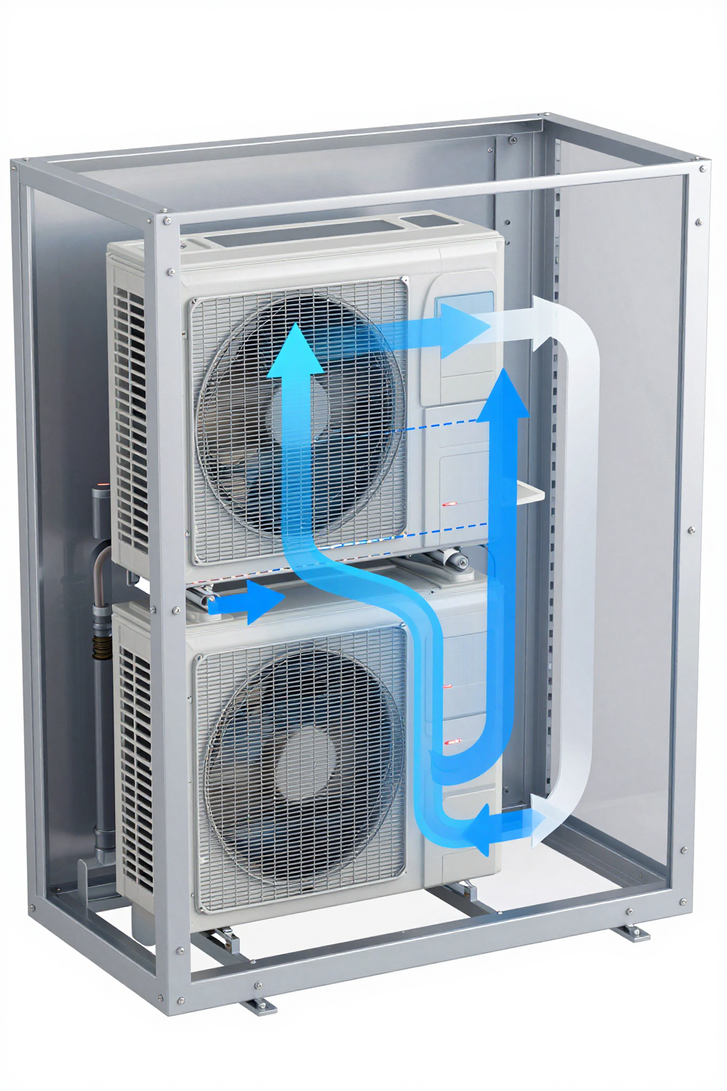
- Thermal Short-Cycling: If the cold air discharge from the cooling unit is blocked by cabling or components, it recirculates immediately to the intake. The sensor reads “cold,” the compressor turns off, and the rest of the enclosure overheats.
- Inrush Current Trips: DC compressors have starting currents. If wiring is undersized or power supplies lack peak capacity, the unit may fail to start, triggering a fault loop.
- Vibration Fatigue: On mobile equipment, rigid copper piping in poorly supported cooling units can work harden and crack, leaking refrigerant.
Engineering Fundamentals: The Physics of Sealed Cooling
Understanding the “why” behind the checklist ensures better decision-making. The primary challenge in sealed enclosure cooling is rejecting heat without exchanging air.
Temperature Headroom (Delta T)
In an open-loop system (fans), you rely on the temperature difference between inside and outside to move heat. As the outside gets hotter, your ability to cool diminishes linearly. In a vapor-compression system (like the Micro DC Aircon series), the compressor creates its own artificial temperature difference. The evaporator coil gets very cold (often 0°C to 10°C), creating a massive “temperature headroom” that sucks heat out of the enclosure air rapidly, even if it is 50°C outside.
Condensate Management
When you cool air, you dehumidify it. In a sealed enclosure, moisture from the initial air volume (and any ingress) will condense on the cold evaporator coil. A proper integration strategy must account for where this water goes. It typically drips into a collection tray and is either drained externally or evaporated. Ignoring this leads to water pooling at the bottom of your expensive electronics cabinet.
Performance Data & Verified Specs
When selecting a unit for your enclosure cooling integration checklist, rely on verified parameters. The following models from the Micro DC Aircon series are frequently used in these applications due to their 12V/24V/48V compatibility and compact footprint.
| Model (Pro Series) | Voltage | Nominal Cooling Capacity | Refrigerant | Compressor Type |
|---|---|---|---|---|
| DV1910E-AC | 12V DC | 450W | R134a | BLDC Inverter Rotary |
| DV1920E-AC | 24V DC | 450W | R134a | BLDC Inverter Rotary |
| DV1930E-AC | 48V DC | 450W | R134a | BLDC Inverter Rotary |
| DV3220E-AC | 24V DC | 550W | R134a | BLDC Inverter Rotary |
Note: Capacity varies based on ambient temperature and RPM settings. These units utilize integrated driver boards for variable speed control, allowing the system to throttle down when the heat load decreases, saving battery power.
Field Implementation Checklist
This section details the physical integration steps required to ensure the specs above translate to reliable performance.
1. Mechanical Mounting & Orientation
- Vertical Alignment: Rotary compressors rely on oil sumps for lubrication. Ensure the unit is mounted within 30 degrees of vertical (check specific model tolerances) to prevent oil starvation.
- Flange Stiffness: The enclosure wall must be rigid enough to support the unit’s weight (typically 5–8 kg for micro units) without flexing. Flexing can compromise the gasket seal. Use a backing plate if the enclosure wall is thin gauge steel or plastic.
- Vibration Isolation: For mobile applications, use nyloc nuts and consider rubber isolation washers between the unit flange and the enclosure to dampen high-frequency vibration.
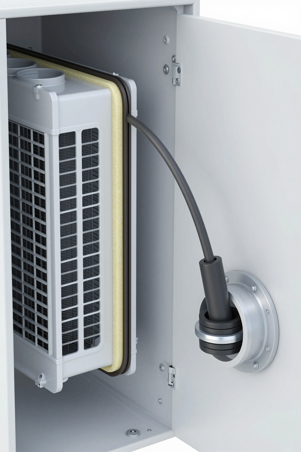
2. Sealing Strategy
Closed-loop designs avoid air exchange, but overall ingress protection still depends on gasket integrity, cable glands, and installation quality.
- Gasket Compression: Do not over-torque mounting bolts. Over-compression can crush the closed-cell foam gasket, reducing its rebound memory and leading to leaks later. Follow the torque spec (often low, e.g., 2–4 Nm).
- Cable Glands: Ensure all cable entries into the enclosure use rated glands. A single open hole defeats the purpose of a sealed air conditioner.
3. Airflow & Cable Routing
- Intake Clearance: Maintain at least 50–100mm of clearance in front of the condenser (external) and evaporator (internal) fans.
- Avoid Short-Cycling: Do not route large cable bundles directly across the air outlet. Use wire ducting to route cables around the airflow path.
- Hot Spot Targeting: Position the cold air outlet near the hottest components (e.g., VFDs, CPUs) but avoid blowing freezing air directly onto sensitive optical components which might fog up.
4. Electrical & Power
- Wire Sizing: Size power cables for the maximum current, not the average. Voltage drop over long cable runs (common in telecom towers) can trigger the unit’s low-voltage cutoff protection.
- Fusing: Always install a fuse or breaker on the positive line, sized approx 1.25x to 1.5x the max rated current.
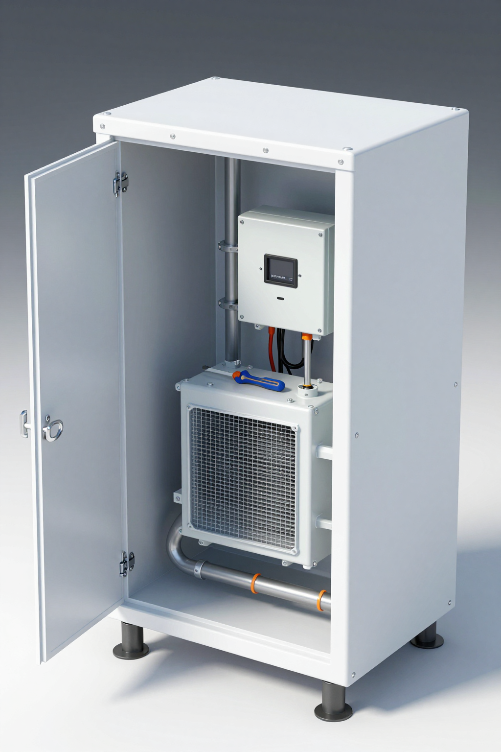
5. Service Access Enclosure Design
Designing for the technician is as important as designing for the heat load. A well-planned service access enclosure layout reduces truck roll time.
- Filter Access: If the external side has a filter (for dust), can it be changed without opening the secure internal cabinet?
- Controller Port: Is the driver board’s diagnostic port accessible? Some Micro DC Aircon units allow error code reading via a simple LED blink code or TTL connection. Ensure this isn’t buried behind a mounting plate.
- Condensate Drain: Route the drain tube so it is visible. A clog here is a common failure mode; seeing water drip confirms the unit is dehumidifying.
Expert Field FAQ
Q: Can I run a 24V Micro DC Aircon directly from a solar panel?
A: Typically, no. You need a battery buffer. Solar output voltage fluctuates wildly with cloud cover. The compressor controller requires a relatively stable DC voltage range to operate reliably.
Q: How do I calculate the exact heat load?
A: Sum the dissipated power (Watts) of all internal components. Do not use the “rated power” of the device, but the “heat dissipation” or efficiency loss. For example, a 1000W VFD might only dissipate 30W–50W of heat.
Q: What happens if the ambient temperature exceeds the unit’s rating?
A: Most DC compressors will continue to run but with reduced capacity. However, if the condenser cannot reject heat (e.g., 60°C+ ambient), the high-pressure safety switch may trip to protect the compressor.
Q: Do I need a heater as well?
A: In climates with freezing nights, yes. While the electronics generate heat, a cold start at -20°C can damage components. Some Micro DC Aircon units have integrated heater control logic.
Q: How often should I clean the external coil?
A: It depends on the site. In a clean server room, never. In a cotton mill or desert, potentially monthly. Using a hydrophobic coating on the fins can help reduce adhesion of dust.
Q: Why is my enclosure sweating on the outside?
A: This is rare but happens if the internal temperature is extremely cold and the outside is humid. It usually indicates you are cooling the enclosure far below the dew point. Adjust the setpoint higher (e.g., 25°C or 30°C) to save energy and prevent sweating.
Conclusion & System Logic
Successful deployment in harsh environments is rarely about finding a “magic box” that solves all problems. It is about the systematic application of physics and best practices. By following a strict enclosure cooling integration checklist, you ensure that the thermal management system supports the equipment rather than becoming a liability.
Compressor-based cooling, such as the Micro DC Aircon series, offers the high Delta T and sealing properties required for modern off-grid and industrial electronics. However, its performance is inextricably linked to the quality of the mechanical and electrical integration. A sealed enclosure that leaks is just a humidity trap; a powerful compressor with a blocked airway is just a heater.
Request Sizing & Integration Support
Don’t guess on thermal loads. Our engineering team can assist with sizing and integration advice for your specific chassis. When requesting support, please provide:
- Ambient Conditions: Max temperature and solar exposure.
- Target Internal Temp: Max allowable component temperature.
- Heat Load Estimate: Total watts dissipated.
- Power Source: Voltage (12/24/48V) and current limits.
- Sealing Target: IP/NEMA requirement.
- Service Interval: Expected maintenance frequency.


0 条评论