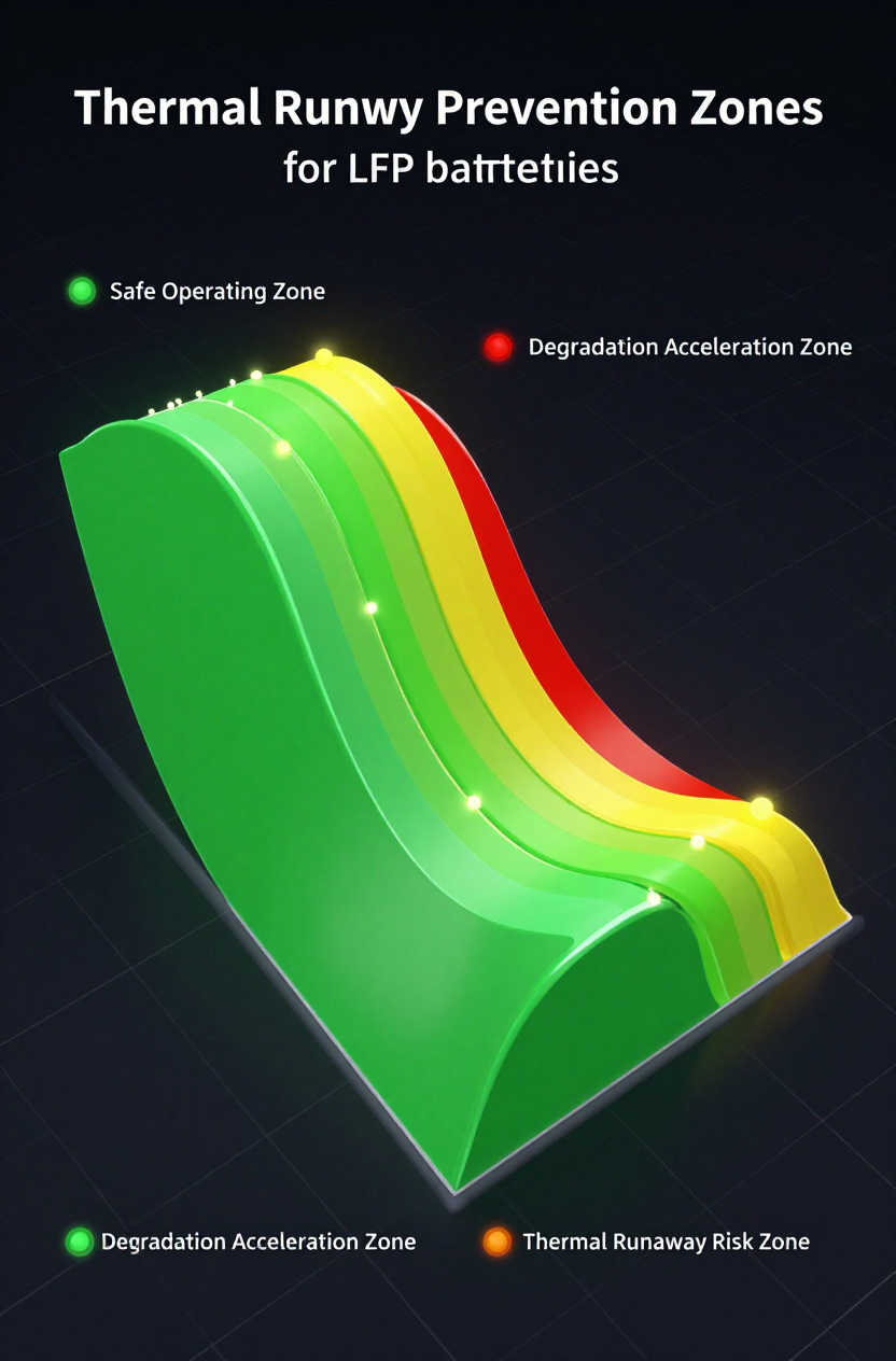
The Physics of Risk in High-Density Storage
As energy storage density increases, the thermal management of Battery Energy Storage Systems (BESS) transitions from a secondary consideration to a primary safety constraint. For engineers designing 48V DC systems—whether for telecom base stations, remote monitoring, or off-grid industrial power—the challenge is no longer just keeping components “cool enough” to operate. The goal is precise thermal regulation to prevent accelerated degradation and the catastrophic risk of thermal runaway.
In many outdoor deployments, passive cooling methods are reaching their physical limits. The ambient temperatures in deployment zones often exceed the safe operating limits of Lithium Iron Phosphate (LFP) or Nickel Manganese Cobalt (NMC) cells. When the external air is 45°C, a filter fan cannot bring the internal cabinet temperature down to the optimal 25°C range required for maximum cycle life. This thermal gap is where 48V battery cabinet cooling becomes a critical subsystem decision.
This article analyzes the engineering logic behind active cooling integration, specifically focusing on direct DC vapor compression technology. We will examine the layout strategies, sensor placements, and thermal loads that define a resilient system, moving beyond simple datasheet specs to the operational realities of harsh environments.
Deployment Context: Where Passive Cooling Fails
To understand the necessity of active cooling, we must look at the specific constraints of common deployment scenarios. These are not hypothetical lab conditions but the gritty realities of field operations.
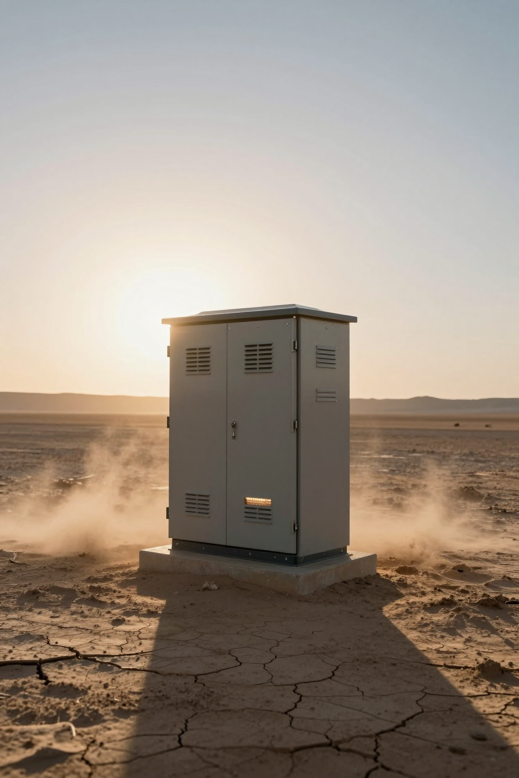
Scenario A: The Desert Telecom Tower
Consider a 48V telecom enclosure in an arid region. The ambient temperature peaks at 50°C during the day. The enclosure houses a rectifier shelf and three strings of 48V LFP batteries.
Constraints:
- Solar Loading: Direct sunlight adds a significant radiative heat load (often >200W depending on surface area and color).
- Dust Ingress: Fine sand prohibits the use of open-loop cooling (fans) without heavy filtration, which clogs rapidly, reducing airflow and leading to thermal shutdown.
- Power Source: The system runs on a 48V DC bus. Using an AC air conditioner would require an inverter, introducing conversion losses (typically 10-15%) and an additional point of failure.
Scenario B: Roadside Traffic Control UPS
A compact cabinet located near a highway, subjected to vibration, exhaust fumes, and salt spray (in coastal areas).
Constraints:
- Corrosion: Salt and pollutants demand a sealed enclosure (NEMA 4X / IP55 or higher).
- Maintenance Access: Truck rolls are expensive. Filter changes for fans are operationally unsustainable.
- Thermal Runaway Risk: High discharge rates during grid outages generate internal heat spikes that must be rejected immediately to prevent cell-to-cell propagation.
Decision Matrix: Selecting the Cooling Architecture
When evaluating thermal management options, engineers must weigh cooling capacity against power consumption and maintenance liabilities. The following matrix compares the three dominant technologies for small-to-mid-sized cabinets.
| Criteria | Filter Fans (Passive) | Thermoelectric (TEC/Peltier) | Micro DC Aircon (Compressor) |
|---|---|---|---|
| Sub-Ambient Cooling | No (Always T_internal > T_ambient) | Yes | Yes (High Capacity) |
| Sealed Enclosure (IP/NEMA) | No (Open Loop) | Yes (Closed Loop) | Yes (Closed Loop) |
| Cooling Capacity Range | Dependent on Airflow/Delta T | Typically <200W | 100W – 900W+ |
| Efficiency (COP) | High (but limited physics) | Low (0.5 – 0.7) | High (2.5 – 3.5) |
| Maintenance Risk | High (Filter Clogging) | Low (Solid State) | Low (Sealed System) |
| Best Fit Scenario | Indoor / Clean / Low Heat Load | Small Enclosures / Low Heat | High Heat / Harsh Ambient / Solar |
Implication: For outdoor 48V battery cabinets where ambient temperatures rival or exceed the battery’s max limit, fans are physically incapable of cooling. TECs are viable only for very small loads due to their power inefficiency. For robust 48V battery cabinet cooling in harsh environments, micro-compressor systems offer the necessary balance of capacity and efficiency.
Quick Selection Rules
- Rule 1: If T_ambient_max ≥ T_battery_limit, you must use active cooling (Compressor or TEC). Fans cannot cool below ambient.
- Rule 2: If the heat load exceeds 200W and power budget is tight, avoid TECs. The current draw will be 3-4x higher than a compressor-based solution for the same cooling effect.
- Rule 3: If the environment contains conductive dust or salt fog, specify a closed-loop system (IP55 minimum) to protect the BMS and terminals.
- Rule 4: If the power source is native 48V DC, specify a 48V DC cooling unit to eliminate inverter failure points.
- Rule 5: If thermal runaway prevention is a safety mandate, ensure the cooling unit has sufficient reserve capacity to handle the heat spike of a high C-rate discharge.
Failure Modes: The Unseen Enemies of Uptime
In the field, cooling systems rarely fail because the compressor explodes. They fail due to integration oversights and environmental attrition. Understanding these failure modes is key to designing a resilient system.
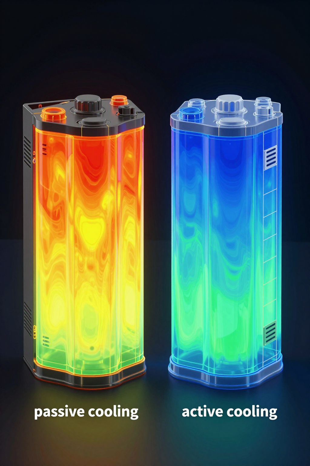
1. The “Hot Pocket” Stratification
Heat rises. In a tall, narrow battery cabinet, the top battery module often operates 5-10°C hotter than the bottom module if airflow is not actively managed. This thermal imbalance causes the top string to degrade faster, unbalancing the entire bank and confusing the BMS. Effective 48V battery cabinet cooling requires directed airflow that scrubs heat from the top of the cabinet or a return-air path that pulls from the hot zone.
2. Filter Clogging & Thermal Shutdown
For fan-based systems, a 50% clogged filter can reduce airflow by 70-80% depending on the fan curve. This leads to a rapid rise in internal temperature, triggering the battery’s thermal protection disconnect. The system goes offline exactly when it is needed most.
3. Condensation and Dew Point
Active cooling introduces the risk of condensation. If a cooling unit runs at 100% capacity while the cabinet is opened for maintenance, or if the enclosure leaks humid air, moisture can condense on cold surfaces. If those surfaces are near the DC busbars, a short circuit can occur. Proper condensate management (drain lines or evaporators) is non-negotiable.
4. Inrush Current Trips
Some cooling units have high inrush currents during compressor startup. On a 48V bus shared with sensitive telecom gear, a massive current spike could trigger a breaker or cause a voltage dip that reboots the router. Soft-start BLDC drivers are essential to mitigate this risk.
Engineering Fundamentals: The Thermodynamics of Reliability
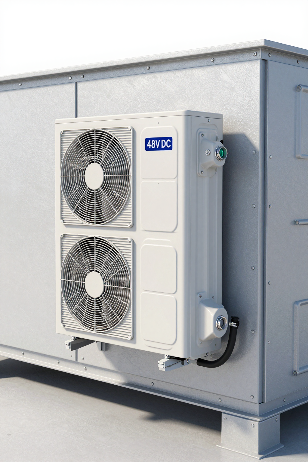
Why choose a vapor compression cycle for a battery cabinet? The answer lies in the latent heat of vaporization. A phase-change system (refrigerant turning from liquid to gas) can absorb significantly more energy per unit of mass than simple air convection or the Peltier effect.
In a Micro DC Aircon, the compressor circulates a refrigerant (like R134a) which absorbs heat from the cabinet air via the evaporator coil. This process is driven by a BLDC (Brushless DC) motor. The advantage of the BLDC inverter is variable speed control. The compressor can ramp up to 4,000 RPM to handle a sudden heat load (like a fast-charge cycle) and then ramp down to 2,000 RPM to maintain steady-state temperature. This modulation reduces the “on/off” cycling that stresses batteries and stabilizes the internal temperature, which is crucial for accurate voltage sensing.
Furthermore, operating directly on 48V DC means the cooling system is harmonized with the battery bank. There is no need to invert DC to AC to run a traditional compressor, saving energy and space. The system effectively runs off the very energy source it is protecting, creating a self-sustaining loop as long as the battery has charge.
Performance Data: Verified Specifications
When specifying a unit, vague marketing terms like “high capacity” are dangerous. Engineers need hard data. Below are the verified specifications for the DV series Micro DC Aircon, specifically the 48V variant suitable for telecom and BESS applications.
| Parameter | DV1930E-AC (Pro) |
|---|---|
| Voltage | 48V DC (Nominal) |
| Cooling Capacity | 450W (Nominal) |
| Refrigerant | R134a |
| Compressor Type | Miniature BLDC Rotary |
| Control | Integrated Driver Board (Inverter) |
| Dimensions | Compact (Varies by integration) |
Note: Cooling capacity varies based on ambient temperature and internal setpoint. The 450W rating is typical at standard test conditions.
For applications requiring different voltages or form factors, the Micro DC Aircon series offers flexibility, but the 48V configuration is the standard for modern DC microgrids.
Field Implementation: Layout and Sensor Placement
The physical integration of the cooling unit is as important as the unit itself. Poor layout can negate the benefits of a high-performance chiller.
1. Sensor Placement for Safety
Where you place the temperature sensor dictates how the system reacts.
Bad Practice: Placing the sensor directly in the cold air stream of the AC unit. This causes “short cycling,” where the AC thinks the cabinet is cold and shuts off, while the batteries remain hot.
Best Practice: Place the control sensor at the return air inlet of the cooling unit (the hottest air). Additionally, for thermal runaway prevention, independent sensors should be placed between battery modules. While the AC unit may not read these directly, the BMS should monitor them and trigger a “max cool” mode on the AC if a specific cell block spikes in temperature.
2. Airflow Management
Create a defined “cold aisle” and “hot aisle” even inside a small cabinet. Use baffles to force cold air to travel through the battery rack before returning to the cooling unit. Without baffles, cold air will take the path of least resistance, bypassing the battery modules entirely.
3. Sealing and Insulation
A Micro DC Aircon is a closed-loop system. If the cabinet is not sealed (IP55 or better), the unit will attempt to cool the entire outdoors. This leads to continuous 100% duty cycle operation, eventual icing of the evaporator, and failure. Ensure all cable glands are sealed and the cabinet walls are insulated to minimize solar gain.
Expert Field FAQ
Q: Can I power the cooling unit directly from the battery bank it is cooling?
A: Yes, this is the standard topology for 48V systems. However, you must configure a Low Voltage Disconnect (LVD) to cut power to the cooling unit before the battery is drained to a critical level, ensuring the BMS and comms remain online.
Q: How does 48V battery cabinet cooling impact the overall autonomy of the site?
A: While active cooling draws power, it typically extends autonomy in the long run by preserving battery capacity. A hot battery degrades and loses capacity permanently. The power draw of a Micro DC Aircon (e.g., 100-200W average) is usually a small fraction of the total site load.
Q: What happens if the cooling unit fails?
A: In a properly designed system, the BMS should detect the temperature rise. The system logic should then derate the load (reduce charging/discharging current) to minimize heat generation until service arrives.
Q: Is R134a the only option?
A: No, the series supports R290 and R1234yf, which have lower Global Warming Potential (GWP). However, R134a remains common for its stability and widespread serviceability.
Q: How do I prevent condensation on the battery terminals?
A: Set the cooling setpoint above the dew point, or use a unit with a reheat function. More commonly, ensure the cabinet is sealed against humidity ingress and that the cooling unit has a proper condensate drain routed outside the enclosure.
Q: Does the compressor cause vibration issues for the batteries?
A: Miniature DC compressors are rotary type and have very low vibration compared to reciprocating compressors. However, using rubber isolation mounts is standard practice to decouple any residual vibration from the chassis.
Conclusion & System Logic
Selecting the right 48V battery cabinet cooling solution is a balance of physics and pragmatism. Passive methods like fans are simple but fail when ambient temperatures rise or air quality drops. Thermoelectric coolers offer solid-state reliability but struggle with efficiency at higher loads. For most high-density, outdoor, or harsh-environment BESS deployments, the Micro DC Aircon provides the necessary thermal authority to maintain safe operating temperatures and mitigate the risks of thermal runaway.
The goal is a “set and forget” system where the cooling architecture protects the most expensive asset in the enclosure—the battery—without becoming a maintenance burden itself. By adhering to strict sealing protocols, optimizing sensor placement, and sizing the capacity correctly, engineers can ensure their 48V systems survive the heat.
Request Sizing Assistance
To ensure your cooling solution matches your specific heat load and environmental constraints, our engineering team can assist with a detailed sizing calculation. Please prepare the following inputs:
- Target Internal Temperature: (e.g., 25°C)
- Maximum Ambient Temperature: (e.g., 50°C + Solar Load)
- Total Heat Load: (Watts, including battery I²R losses and active equipment)
- Voltage Available: (e.g., 48V DC, range 42-58V)
- Cabinet Dimensions & Insulation: (H x W x D, wall thickness)
- Sealing Target: (IP55, NEMA 4, etc.)


0 条评论