For control engineers and system integrators, the shift from fixed-speed cooling to variable speed technology represents more than just an efficiency upgrade—it is a fundamental change in how thermal loads are managed in critical applications. In the world of precision cooling for electronics, medical devices, and mobile telecom units, the “bang-bang” (on/off) control method often falls short. It introduces thermal hysteresis, creates massive inrush current spikes, and stresses power supplies. The variable speed dc compressor has emerged as the standard solution for these challenges, offering a way to match cooling capacity dynamically to the heat load.
However, integrating these compressors requires a shift in control strategy. It is not merely a matter of supplying power; it involves managing 0-5V or PWM signals, tuning PID loops, and understanding the mechanical limits of the compressor itself, such as minimum speeds for oil lubrication and resonance avoidance. This article explores the engineering realities of deploying variable speed vapor compression technology in harsh, off-grid, or mobile environments.
The Core Decision: Precision vs. Complexity
The primary driver for selecting a variable speed solution is usually the need for tighter temperature control or limited power availability. In a fixed-speed system, the compressor runs at 100% capacity until the setpoint is reached, then shuts off. This creates a sawtooth temperature profile. A variable speed system modulates the compressor’s RPM (Revolutions Per Minute) to maintain a steady state, effectively flattening the temperature curve.
Yet, this precision comes with an integration cost. You are no longer just wiring a thermostat to a relay. You are integrating a BLDC (Brushless DC) driver, managing logic signals, and ensuring your control algorithm doesn’t drive the system into instability. The following sections detail how to navigate these trade-offs.
Deployment Context: Where Variable Speed Matters
To understand the practical application, let’s look at two distinct scenarios where the specific attributes of DC inverter technology are non-negotiable.
Scenario 1: Mobile Medical Cold Chain
Consider a portable vaccine transport unit powered by a battery bank. The payload must remain between 2°C and 8°C.
Constraints:
- Power Budget: Limited battery capacity means every watt counts.
- Inrush Current: A hard start from a fixed-speed compressor could trip the battery protection circuit (BMS).
- Precision: Temperature excursions below 0°C ruin the payload.
In this context, a variable speed dc compressor allows the system to “soft start,” ramping up slowly to avoid current spikes. Once the target temperature is reached, the compressor slows down to a low-RPM maintenance mode, consuming significantly less power than a fixed-speed unit cycling on and off.
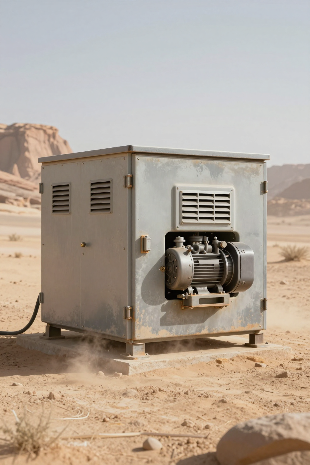
Scenario 2: Outdoor Telecom Enclosure (Desert Deployment)
A sealed enclosure housing 5G equipment in a desert environment faces extreme diurnal temperature swings—from 5°C at night to 50°C during the day.
Constraints:
- Heat Load: Varies wildly based on traffic (internal load) and sun exposure (external load).
- Sealing: The enclosure must remain NEMA 4/IP65 compliant to prevent dust ingress.
- Reliability: Remote sites mean truck rolls for maintenance are prohibitively expensive.
Here, the variable speed capability allows the cooling system to adapt. During the midday heat peak, it runs at maximum RPM (e.g., 4,000–6,000 RPM). At night, it drops to minimum RPM (e.g., 2,000 RPM) rather than cycling off, preventing condensation issues associated with rapid cooling and heating cycles.
Decision Matrix: Technology Selection
When evaluating cooling architectures, engineers must weigh the benefits of variable speed against other common methods like fixed-speed DC compressors or Thermoelectric Coolers (TECs/Peltier). The table below outlines the trade-offs.
| Criteria | Fixed Speed DC Compressor | Variable Speed DC Compressor | Thermoelectric (TEC) |
|---|---|---|---|
| Temperature Stability | Low (Hysteresis depends on deadband) | High (Can achieve ±0.5°C or better) | Very High (Can achieve ±0.1°C) |
| Energy Efficiency (COP) | Moderate (2.0–3.0 typical) | High (3.0–4.0+ at partial load) | Low (0.5–0.8 typical) |
| Inrush Current | High (Locked Rotor Amps) | Low (Soft Start via Inverter) | None (Resistive load behavior) |
| Cooling Capacity | Fixed (e.g., 450W) | Variable (e.g., 100W–550W) | Low (Typically <200W practical) |
| Control Complexity | Simple (Relay/Thermostat) | Moderate (0-5V/PWM, PID Loop) | Moderate (PWM H-Bridge) |
| Best Fit Scenario | Stable loads, lower cost sensitivity | Battery power, fluctuating loads, precision | Low heat load, extreme precision, no vibration |
Implication: If your power budget is tight (battery/solar) or your heat load fluctuates significantly, variable speed is the defensible engineering choice. If the load is tiny (<50W) and precision is paramount, TECs may apply, but they suffer efficiently at higher loads.
Quick Selection Rules
Use these rules of thumb during your initial design review:
- If the power source is a battery with strict current limits, then a variable speed compressor is required for its soft-start capability to prevent BMS tripping.
- If the target temperature tolerance is tighter than ±2°C, then fixed-speed cycling will likely fail; use variable speed with PID control.
- If the application requires sub-ambient cooling in a high-ambient environment (>40°C), then ensure the compressor’s displacement is sized for the worst-case Delta T, not just the average.
- If the system must operate silently (e.g., bedside medical), then variable speed allows for lower RPM operation, significantly reducing acoustic noise and vibration.
- If the cooling load is consistently below 20% of the compressor’s nominal capacity, then beware of short-cycling or oil return issues; verify the minimum safe RPM.
Failure Modes & “Unseen Enemies”
While variable speed technology improves reliability by reducing start/stop stress, it introduces specific failure modes that control engineers must mitigate.
- Oil Return Starvation: Vapor compression systems rely on the refrigerant flow to carry oil back to the compressor. Running at very low RPMs (e.g., below 1,800 RPM) for extended periods can reduce flow velocity, causing oil to trap in the evaporator. Mitigation: Program an “oil recovery cycle” that ramps the compressor to high speed for a few seconds every few hours.
- Resonance Frequencies: Every mechanical system has a natural frequency. A variable speed compressor sweeps through a wide range of RPMs. It may hit a frequency that causes the enclosure or piping to resonate dangerously. Mitigation: Identify resonance bands during testing and program the controller to skip those specific RPM ranges.
- Inverter Overheating: The BLDC driver board generates heat, especially at high currents. If the driver is located inside a sealed enclosure without a thermal path to the outside, it can overheat and shut down. Mitigation: Ensure the driver board is heatsinked to the chassis or located in the airflow path.
- Sensor Lag: In a variable speed system, if the temperature sensor is placed too far from the heat source, the PID loop may oscillate, causing the compressor to hunt for the correct speed. Mitigation: Place sensors directly on the critical component or at the return air inlet.
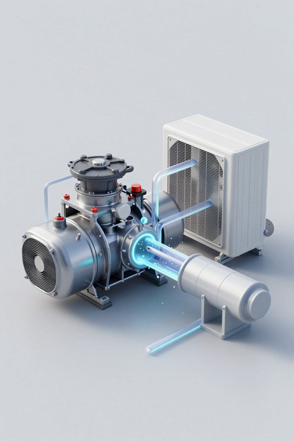
Engineering Fundamentals: Why Variable Speed Wins on Efficiency
The efficiency advantage of a variable speed dc compressor is rooted in the thermodynamics of the vapor compression cycle. The Coefficient of Performance (COP) is the ratio of cooling capacity (Q) to power input (W). In a fixed-speed system, the compressor always runs at maximum displacement, creating the highest possible pressure difference (compression ratio) between the evaporator and condenser.
However, the compression ratio is the enemy of efficiency. The higher the pressure lift, the more work the motor must do. When a variable speed compressor slows down to match a partial load, two things happen:
- Mass Flow Reduction: The refrigerant flow rate decreases, which effectively “oversizes” the heat exchangers (condenser and evaporator) relative to the flow. This reduces the temperature difference required to transfer heat, lowering the condensing pressure and raising the evaporating pressure.
- Compression Ratio Drop: With a lower condensing pressure and higher evaporating pressure, the compression ratio drops. The compressor does less work per unit of cooling, significantly boosting COP.
This “partial load efficiency” is why variable speed systems can achieve COPs of 4.0 or higher at 50% speed, whereas they might only hit 2.5 at 100% speed. For battery-powered applications, this extends runtime dramatically.
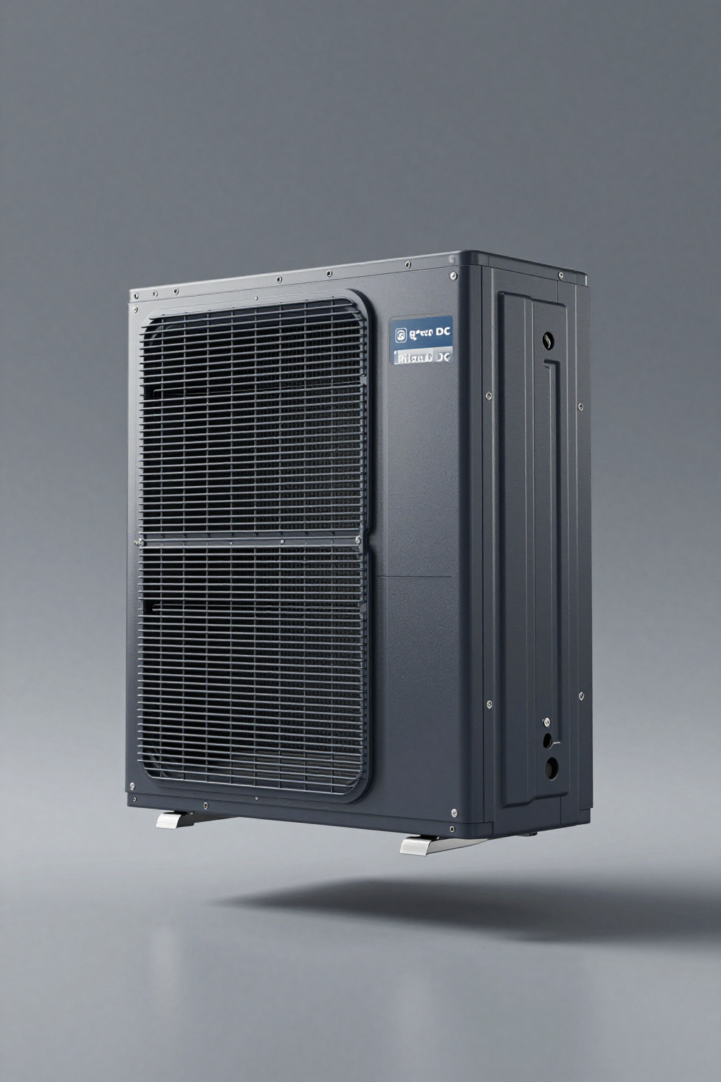
Performance Data & Verified Specs
When selecting a unit, it is critical to look at the specific voltage and capacity ranges. The following table highlights verified specifications for Arctic-tek’s Micro DC Aircon and Miniature DC Compressor series. Note the voltage options and refrigerant types, which dictate compliance and power architecture.
| Series / Model Example | Voltage (DC) | Nominal Cooling Capacity | Refrigerant | Compressor Type |
|---|---|---|---|---|
| Micro DC Aircon (DV1910E-AC) | 12V | 450W | R134a | Rotary BLDC Inverter |
| Micro DC Aircon (DV1920E-AC) | 24V | 450W | R134a | Rotary BLDC Inverter |
| Micro DC Aircon (DV3220E-AC) | 24V | 550W | R134a | Rotary BLDC Inverter |
| Miniature DC Compressor (QX1901VDL) | 12V | 100W–400W (Variable) | R134a | Rotary BLDC |
| Miniature DC Compressor (QX1903VDL) | 48V | 100W–500W (Variable) | R134a | Rotary BLDC |
| Micro Liquid Chiller (KVB150Z) | 24V / 48V | ~150W–400W | R134a | Rotary BLDC |
Note: Capacity varies based on RPM setting and ambient conditions. The “Nominal” value typically represents standard test conditions (e.g., LBP or HBP standards).
Field Implementation Checklist
Successful integration of a Micro DC Aircon or standalone compressor requires attention to detail across mechanical, electrical, and control domains.
Electrical Integration
- Wire Sizing: Even with soft start, ensure wiring is sized for the maximum continuous current (MCC) to prevent voltage drop. DC motors are sensitive to voltage sag, which can trigger under-voltage faults in the driver.
- Power Supply: If using an AC/DC power supply, ensure it has sufficient overhead. A 24V compressor might draw 15A at peak load; a 20A supply is the minimum recommended safety margin.
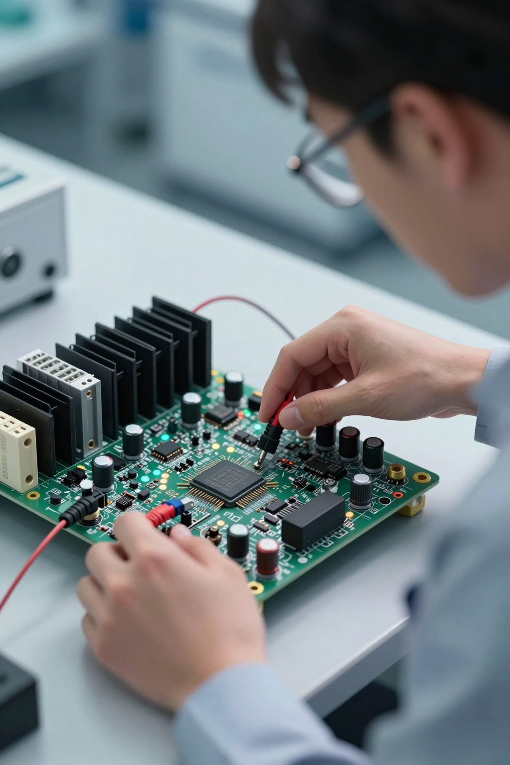
Control Logic (PID Tuning)
- Proportional (P): Sets the reaction strength. Too high, and the compressor oscillates (hunts). Too low, and it reacts too slowly to heat loads.
- Integral (I): Corrects the steady-state error. Essential for bringing the temperature exactly to the setpoint.
- Derivative (D): Predicts future error. Often set to zero or very low in thermal systems due to the slow nature of temperature change.
- Dead Band: Even with variable speed, define a small dead band (e.g., 0.5°C) where the compressor speed does not change, to prevent constant micro-adjustments that wear out the logic or driver.
Mechanical & Thermal
- Vibration Isolation: Use rubber grommets (typically provided) to mount the compressor. Rigid mounting transmits vibration to the chassis, creating noise and potential fatigue cracks in refrigerant lines.
- Airflow Management: Ensure the condenser fan speed is also managed or set to a sufficient constant speed. A variable speed compressor with a choked condenser airflow will suffer from high head pressure and poor efficiency.
Expert Field FAQ
Q: What is the minimum speed I can run a variable speed dc compressor?
A: Typically, the minimum safe speed is around 2,000 RPM. Below this, the oil pump inside the rotary compressor may not generate enough pressure to lubricate the bearings, and refrigerant velocity may drop too low for oil return. Always check the specific model’s datasheet.
Q: Can I run these compressors without a controller?
A: No. The BLDC motor requires a driver board (inverter) to commutate the phases. However, some driver boards accept a simple on/off signal (running the compressor at a pre-set fixed speed) if variable control is not needed, effectively mimicking a fixed-speed unit.
Q: How does the inrush current compare to an AC compressor?
A: It is significantly lower. A standard AC compressor might pull 5–6 times its rated current at startup (Locked Rotor Amps). A DC inverter compressor ramps up slowly, typically drawing only slightly more than its rated running current during the ramp-up phase.
Q: What happens if the ambient temperature exceeds the rating (e.g., >55°C)?
A: The driver board usually has thermal protection. If the internal electronics or the compressor shell gets too hot, it will throttle down the speed or shut off completely to protect the hardware. This is a “derating” behavior.
Q: Is variable speed temperature control worth the extra cost for a simple cabinet cooler?
A: If the cabinet is grid-powered and noise/precision are not issues, a fixed-speed unit is often more cost-effective. Variable speed is justified when you need efficiency (battery/solar), precision, or low noise.
Q: Can I use a generic BLDC driver?
A: It is not recommended. The drivers supplied with the DC condensing unit are tuned for the specific back-EMF and inductance characteristics of the compressor motor. Generic drivers may cause synchronization loss or poor efficiency.
Conclusion & System Logic
The transition to variable speed cooling is not just a trend; it is a necessity for modern, efficient, and resilient thermal management systems. By modulating capacity to match the load, a variable speed dc compressor eliminates the electrical and mechanical violence of start-stop cycling. It extends battery life in off-grid applications, reduces acoustic signatures in medical environments, and provides the thermal stability required by sensitive laser and optical components.
However, success lies in the integration. It requires a control strategy that respects the physical limits of the compressor—ensuring oil return, managing resonance, and tuning PID loops for stability rather than just speed. When implemented correctly, these systems offer a “set and forget” reliability that fixed-speed alternatives cannot match.
Request Sizing & Integration Support
Selecting the right compressor and driver combination requires balancing thermal loads with power constraints. To get a defensible recommendation for your specific project, please provide our engineering team with the following inputs:
- Ambient Conditions: Max ambient temperature and solar loading estimates.
- Target Internal Temperature: The maximum allowable temp for your critical components.
- Heat Load Estimate: Total watts dissipated by the internal electronics.
- Power Source: Voltage (12/24/48V) and maximum current limit (Amps).
- Sealing Requirement: IP/NEMA rating target (e.g., IP65, NEMA 4).
- Control Interface: Preferred signal type (0-5V, PWM, RS485).


0 条评论